Fritzing usability
Fritzing is kind of weird, at least for a newbie. I think this was easier than drawing by hand, but I’m not sure. Lots of “try the same thing 10 times until the last time it magically works” and “that doesn’t work; google how to do it; oh look I was trying to do it right; huh now it works?” And then the lines look straight until I export it to PNG. And it says “9 of 10 nets routed - 1 connection still to be routed” and then when I click on it “There are no unrouted connections in this view” but there is no other view.
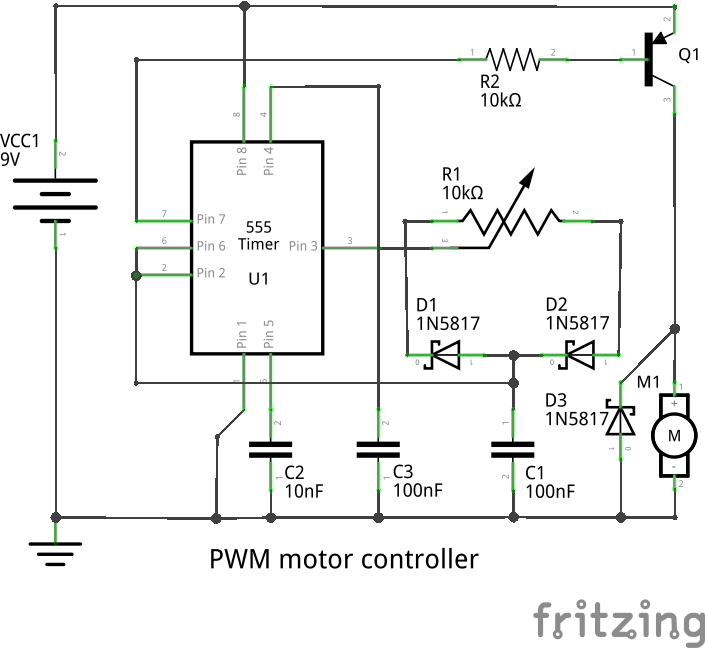
My 7yo son wants to try perfboard soldering to make a motor controller for the motor that he pulled out of a dead CDROM drive. Not entirely clear what the motor is going to do but maybe that’s not the point. ☺
This was based on a design from Rick Bickle to drive a MOSFET but my BS170s haven’t arrived, so I switched the drive side to a PNP transistor, which works fine for this application, such as it is. I admit to having tested it without the freewheel diode…
Richard Hughes July 22, 2014 07:21
Err, you’re a brave man with no suppression diode…
Michael K Johnson July 22, 2014 07:53
Brave isn’t the word that comes to my mind. I just forgot to insert it when I connected the motor…
I first tested it with an LED/resistor load, and still had that connected in parallel with the motor. But that’s not reverse-biased. The LED didn’t burn out and while I have no data sheet for it I suspect its reverse breakdown is lower than the PNP transistor I used so it might have provided some protection?
I’m totally new to this and taking baby steps so I’m sure I’ll make worse stupid mistakes.
Michael K Johnson July 22, 2014 08:45
Oops, didn’t draw the connection between pins 4 and 8 (reset and Vcc). I wonder whether that is the “connection still to be routed” and if so why no ratsnest line?
I’ll have to check when I get home to see whether I left that wire off the breadboard view.
Michael K Johnson July 22, 2014 18:23
Well, that didn’t fix it. I had left it off the breadboard view, which explains the lack of a ratsnest line. But now it says “8 of 9 nets routed” with pins 4 and 8 connected.
Michael K Johnson August 10, 2014 15:28
I started over in kicad. Doing the kicad tutorial first was probably the key to success, but in any case I was able to complete the design, including a PCB design to be stuffed either for PNP transistor or for MOSFET, without much trouble. I think I’ll stick with kicad.
Imported from Google+ — content and formatting may not be reliable