3D printer source of Z-ripple?
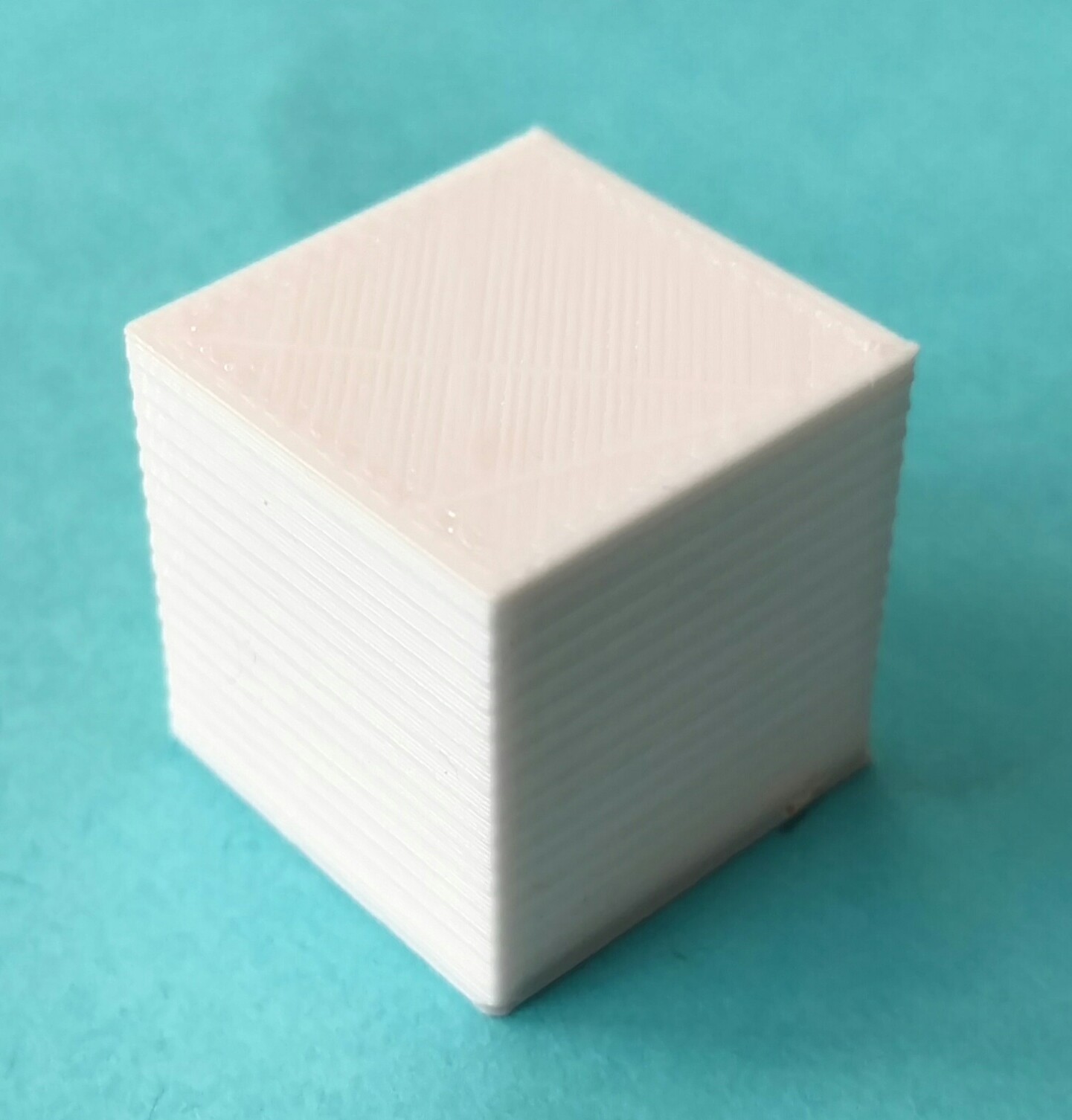
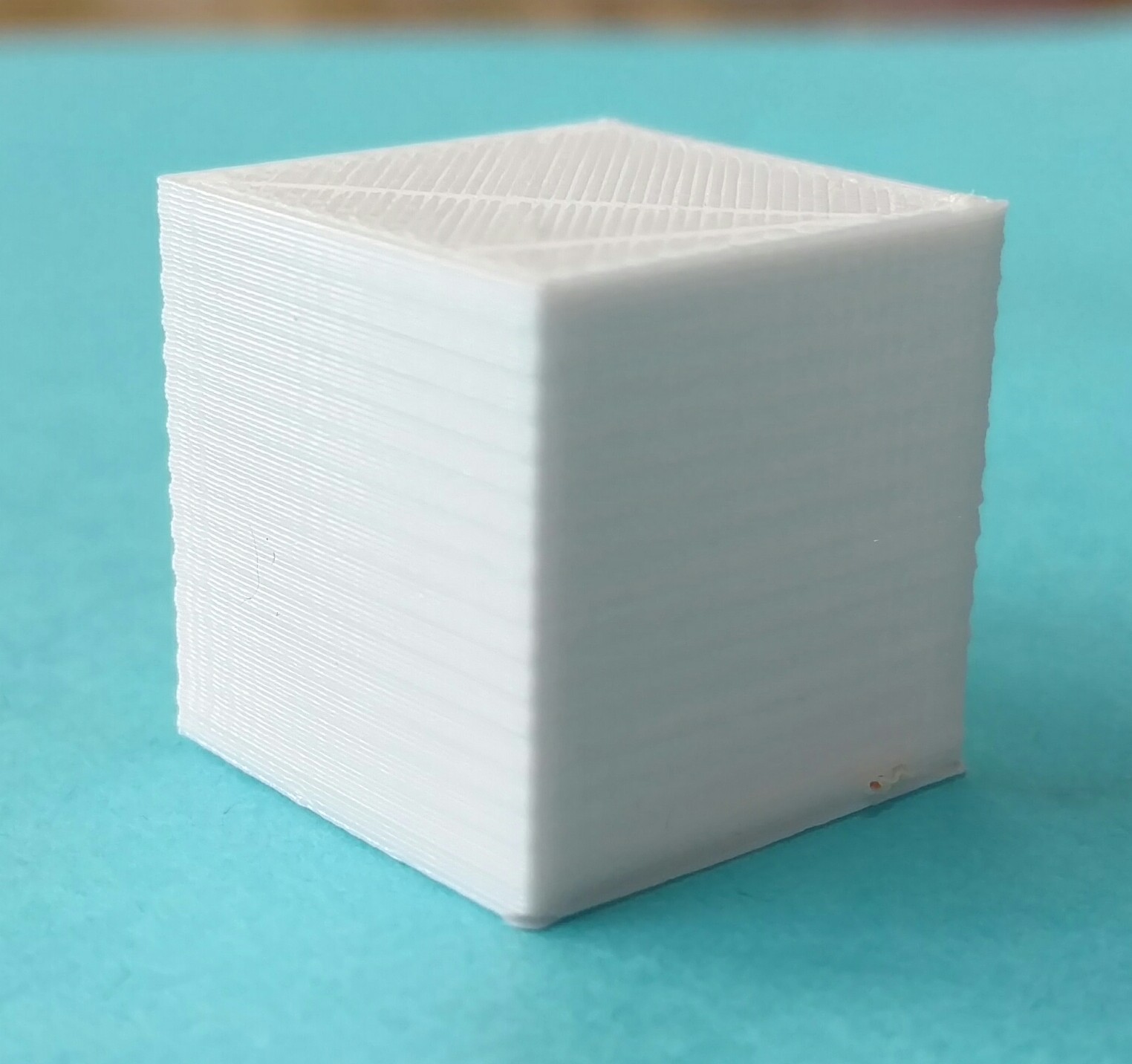
I don’t understand the regular irregularity being produced by my 3d printer. The ripples along both the X and Y axes are consistent in size, repeating every 1.2 mm regardless of whether I am printing 0.2 mm layers (as with this calibration cube) or 0.1 mm layers (I can place the 0.1 mm and 0.2 mm cubes together and the ripples exactly match) and I can’t figure out what they correlate with.
These cubes are supposed to have straight edges. Any ideas about the source of this problem?
#reprap
Eugene Crosser January 16, 2016 09:28
From purely mechanical standpoint, I’d suspect:
-
non-linerarity of the mechanical part that moves the head vertically (belt or screw?)
-
if Z coord passed directly to the step motor, non-linerairy of the motor
-
if Z coord is controlled by feeback from a position sensor, non-linearity of the sensor
in that order.
Michael K Johnson January 16, 2016 09:37
The smooth rods for the Z axis are straight, but the threaded rod isn’t perfectly straight (though not constrained tightly). The threaded rod is M8, and I see that M8x1.25 is normal pitch, so I think you are on to something there! Finally something that correlates!
Acme rod would be a better choice though it would require that I put new firmware on the control board to adjust the pitch. Maybe I can straighten the threaded rods a bit and see if the problem gets any better.
Thanks!
Michael K Johnson January 16, 2016 10:21
Holding one of my calibration cubes against the threaded rod confirmed the pitch match.
Now I just need to wait 4-5 hours for my current print to finish before tearing the printer apart again. Since I got a metal splinter from the threaded rod while assembling the printer, I’ll have to be careful when attempting to straighten them. Also, I greased them to make them stop screaming when lowering the Z axis, so it’s going to be a mess. ☺
Michael K Johnson January 16, 2016 19:46
Sadly, straightening the rods doesn’t seem to have made any difference. They no longer wobble noticeably, but the same gcode prints identically.
If it were really varying pressure against the X and Y axes due to bent Z rod, though, I would expect that each of the layers is the same size and they are just displaced. I’ve been investigating more closely, and I find that instead I have thicker and thinner layers; that the whole cube is thinner in some layers and thicker in others.
I wonder if the thread is uneven, so that layer thickness is uneven? I’m trying prints with varying flow adjustment to see whether they make the effect more or less pronounced.
Before I’m done, I think I’ll have cornered the market in 20mm cubes.
Michael K Johnson January 17, 2016 07:32
Talked to folks on #reprap who asked me about the steps/mm for my printer and linked to http://prusaprinters.org/calculator/ and https://www.evernote.com/shard/s211/sh/701c36c4-ddd5-4669-a482-953d8924c71d/1ef992988295487c98c268dcdd2d687e (a taxonomy of Z axis artifacts). Turns out my printer was set to 2555 steps/mm when for M8 threaded rod it should be 2560. That could create differences in Z height (and thus “squishing out” the thinner layers) due to rounding errors. But setting it to 2560 in the printer interface didn’t make any difference. I don’t know whether they hard-coded it in the firmware they shipped or the threaded rod has a somewhat irregular pitch.
I ordered some fine-pitch 8mm diameter 2mm lead 2mm pitch acme rod (surprisingly hard to find; none of the industrial supply stores I checked had it) which will take weeks to arrive; I couldn’t find any with faster shipping available. It’s easy to get multi-start 8mm lead (travels 8mm per rotation), but should get better accuracy as well as resolution from single-start 2mm lead (travels 2mm per rotation).
Michael K Johnson January 18, 2016 23:16
I built new firmware, including (with help from #reprap folks) making the configuration work on modern marlin instead of the ancient 1.0.0 (with various tweaks) that the vendor shipped. It seems to be generally working, and it definitely has Z steps per mm set to 2560 rather than 2555.
But it still has the same problem. ☹
Michael K Johnson January 24, 2016 16:16
Today I printed a handle for our dinner bell. In order to get honeycomb infill I used slic3r. To go faster I used 0.3mm layers. Everyone noticed that the z-ribbing didn’t show.
I went back to calibration cubes. Started with one sliced with cura at 0.2. I modified temperature while one was printing; no change. I used 0.3 mm instead of 0.2 mm layers in cura, and while the z-ribbing looked trivially different, it had the same pitch and aspect.
Slicing the cube with slic3r at 0.3 mm showed relatively little z-ribbing effect. Slicing the cube with slic3r at 0.2mm showed about the same z-ribbing effect as cura.
So it looks like some difference between how cura and slic3r work affects the z-ribbing at some layer sizes, but it’s only a symptom.
Michael K Johnson January 24, 2016 20:50
Feeling dumb. I guess I checked for play in the left Z threaded rod but not well for play in the right Z threaded rod. The left Z rod is solid, but the right Z rod is rather loose and has some play, and I did less well straightening the right Z rod.
I wrapped teflon joint tape a few times around the right Z rod and the Z-ribbing got better.
Gives me hope that the more accurate T8 single-start precision rod with the precision flanged nut will solve the problem more permanently, after USPS recovers from the snowpocalypse.
Michael K Johnson February 02, 2016 20:58
Replacing the Z rod with single-start T8*2 2mm pitch, 2mm lead, 8mm wide trapezoidal threaded rod seems to have been an improvement.
http://www.amazon.com/gp/product/B018KFH536 was where I found the T8*2 I bought— but now showing as “currently unavailable” so now I don’t know where to point others. (Closest I can find right now is http://www.mpja.com/Leadscrew-Assembly-8mm-X-400mm-Shaft/productinfo/32396+HD/ but that’s 400mm long and three times the cost.)
Now I can really see the vibration from the loose SCS8UU pillow block linear bearings for the Y axis. I taped some metal items to the bed while printing a calibration cube to damp movement partway through printing my calibration cube, and it seemed to improve consistency a bit.
Last night I printed 5 different designs for plastic replacement LM8UU bearings to try in my existing pillow blocks while I wait for my oil-filled bronze bushings and graphite bronze bushings, but the prints probably weren’t high enough quality to use. When the new bushings come, I’ll print some replacement SCS8UU pillow blocks sized for the 12mm OD of the bushings and replace them entirely.
http://www.thingiverse.com/thing:911493 for the bushing pillow blocks. Unless someone else has better suggestions.
Michael K Johnson February 17, 2016 06:24
The oil-filled bronze bushings in those printed pillow blocks chattered, and I couldn’t get them properly aligned to stop chattering, so I gave up for now. If I take this back up, I’ll design something that doesn’t looks like a pillow block.
Imported from Google+ — content and formatting may not be reliable