My Tronxy X5S
Anyone here have a Tronxy X5S? The initial reviews were pretty much unanimous that the corexy kinematics suffered a lot from non-parallel arrangement, but a few folks designed replacement parts to solve that problem, so I bought one.
I was pleasantly surprised that they took the review feedback and pretty much fixed the kinematics. They still call the motors “X” and “Y” but I didn’t see that they had swapped the names as early reviewers found.
The heated bed is still anemic with 12V. But I measured 4 Ohms, so a 20A 24V power supply should be OK. Rumors are that the board they ship can handle 24V, so no need for dual power supplies and a MOSFET board. They still include mostly philips-head screws in the kit. And sadly my copy shipped with a broken build manual, so I’ve asked for an update. (I think I’ve completed the build and am printing, but I’d like to cross-check against the full manual…)
Michael Westbay January 21, 2018 03:24
+Michael K Johnson - I got a Tronxy X5S back in September of last year. I think they have made a number of improvements since then based on customer feedback. The main issue I had was that the X-axis printed a mirror image of everything I gave it. I tried swapping the X and Y connectors and other things to no avail. Oh, and home was to X-max instead of X-min, which I think was a related issue. Mirroring everything in the slicer before my first major upgrade worked, but was a bit annoying.
So the first major upgrade I made was changing from the board it came with to a GT-2560 Rev A controller board. I had asked for TronXY (and Gear Best) a number of times last year, but they only offered to take the printer back if it wasn’t functioning correctly. I got it because I wanted to tinker with it, not return it.
I couldn’t get the LCD panel that came with the X5S to connect to the GT-2560, so I also added a Raspberry Pi with Octoprint to control it all and leave my PC free.
I’ve put on a few other modifications, like the Mega Gantry Plates and some brackets on the corners to keep everything square. If you find that the X-axis isn’t moving perpendicular to the Y, it’s usually due to one of the belts being tighter than the other. The frame, otherwise, seems to keep everything at right angles.
I’ve put some insolation on the heat bed. That brings it up to 40℃ quickly, but I’m getting some sort of error when I try to go higher than that. It’s still a work in progress.
The other thing I’m working on is a part cooling fan that doesn’t take up too much space. The compact design ones on Thingiverse all seem to go to printers with much more space on the side or in the front. I like the large print volume, and don’t want to give up more space than I need.
There are a number of ideas on the Hypercube that I’m also interested in pursuing.
I’ve been having a great time learning with the X5S. That’s really the main purpose I got it, to tinker with something physical since most of the work I’ve done has been in software over the years.
Hope you enjoy it!
Michael K Johnson January 21, 2018 07:05
+Michael Westbay A couple of years ago, I bought a cheap clone i3 kit with the same idea of learning by fixing what ailed it, and that was a success. This is mostly better so far.
I insulated the heat bed with R6.7 fiberglass backed with three layers of aluminum foil and taped to the sides of the bed brackets with aluminum tape, and with that I was able to heat the bed with the provided polycarbonate sheet to 65⁰ in just under 20 minutes. I plan to supplement the polycarbonate sheet with 330x330 glass sheets at least for printing PLA. (I noticed that here in the USA, store employees only seem to be able to cut glass in good ol’ imperial inches, but fortunately 330mm is 13 inches within their limit of accuracy so I don’t have to confuse them with this new-fangled metric system…☺)
The axes as labeled now matched the firmware, and by being sure to connect the LCD ribbon cables right, the LCD worked fine. I was able to use that to print from the LCD.
I ordered corner braces at the same time as the printer, but they are on the slow boat. I have the M5 t-nuts and screws for attaching them when they arrive, though. I definitely want to stiffen the frame.
I’d like to do something different from the mega gantry plates. I was hoping that one of the milled plates from the open hardware parts store would work, but it doesn’t look like it. But the idea of an aluminum plate instead of acrylic is attractive. Clearly, I need to buy a CNC router! ;)
After I bought the i3 clone, I had intended to build a dual-extruder corexy from scratch and started by buying a replicape and beaglebone to run it, but ran short on available time. I expect to switch to using the replicape to print, probably before I convert to a dual extruder.
I already bought a 20A 24V power supply. If 24V cooks the control board, that will accelerate my path to using the replicape! But I’ve heard that it will work.
For cooling, I’ve been thinking of remote cooling using a vacuum pump (hooked up in reverse) and soft silicon tubing, removing all fan mass from the print head. If I do go dual extruders—and I almost certainly will—then offsetting the new mass on the head sounds like a good idea. And it will allow better cooling without impinging on X or Y axes.
I already put Marlin 1.1.8 on my i3 clone, so going back to 1.1.7 for the x5s feels backwards. Also, the way the knob works feels backwards to me too. So I expect to build new firmware for it soon.
Like you, I have spent my life in software and am enjoying tinkering.
Michael K Johnson January 23, 2018 17:51
I heard back from Tronxy: the blank pages in the manual I got were simply blank and not missing content. I never heard back from gearbest request, but Tronxy responded in a day. I’m pleased.
Michael Westbay January 24, 2018 03:26
+Michael K Johnson - My experience with Gear Best and TronXY trying to get the Marlin settings they used was basically a standardized “send it back to us” from Gear Best. I think the TronXY reply said that flashing the board would invalidate the warrantee. At least they addressed the question.
You also mentioned that you got M5 T-nuts for the brackets. I’m pretty sure that mine are all M4 T-nuts. I ordered another bag of 100 from Ali-Express which I used for the brackets and RasPi case and camera rig. I plan on use them to enclose the frame a bit with insolation someday as well. This is the first I’ve ever seen T-nuts, but I love their concept. Learning so much!
Michael K Johnson January 24, 2018 06:33
GearBest posted the firmware for download if you are logged in with a GB account. — Tronxy should have included the firmware on the sd card they shipped with the printer, but I didn’t ask about that when I emailed them because I forgot that I had downloaded it from gearbest before my printer arrived.
All the T-nuts that came with the printer are M4. I ordered 100 M5 drop-in T-nuts for my own purposes. M58 button head screws for the corner brackets, and M510 for mounting 5mm plywood and associated insulation to enclose it for printing ABS.
I have also ordered single-start T82 lead screws and nuts (2mm pitch, 2mm lead) to replace the four-start T88 (2mm pitch, 8mm lead) that was provided with the printer. I ordered 500mm pieces and will cut them down to size when they arrive. Hopefully they arrive straight! ☺ That obviously requires rebuilding firmware to change steps per mm in Z from 1600 to 400.
I do my initial tramming by trimming the bed surface trammed to the bed support rails and rotating the Z axes independently until the bed is roughly trammed in X before I tram in Y and fine tram it in X with the bed level screws. But then I want to adjust the Z end stop, and I’ve found that while adjusting the Z end stop screw I have pushed down on the bed and the Z axis lead screw nearest the end stop screw has moved down slightly, pushing the bed out of tram in X. Ouch. So I plan to switch to T8*2 lead screw. I did that on my i3 and I’ve never had any Z creep on the i3. This is important to me because I want to be able to easily switch bed surfaces with different thicknesses.
I also ordered a pack of T20 6mm belt 5mm axis idlers to remove belt tooth chatter from running the belts over the smooth bearing idlers. I’ll see how that goes.
Tronxy X5S 3D printer ROM firmware
Michael K Johnson January 27, 2018 11:27
The bed measured 4 ohms at room temperature, but 27.2V across it is consuming 15A so 1.8 ohms heated. I’m finding that with a sheet of glass on the bed with room temperature 19°C, I have to set 118° on my (insulated) bed temperature to hit 110° read with an infrared thermometer at the center of the glass, about 108° halfway to the edge, 105° at the middle of the edge, and 101° at the corners. That leads me to think a bed temperature of 120° will give me about the right bed temperature to print ABS.
So far, I’m using a MOSFET board to give 27.2V to the bed, and 12V for everything else. If I dial the power supply down to 24V it takes only 13A (though it of course does not heat as fast) which would leave me 7A headroom for everything else if/when I switch to the replicape.
That encourages me to buy a 24V hot end…
Michael K Johnson January 27, 2018 14:58
It looks like the firmware they provide is a fork off Marlin 1.0.2 from years ago. Since I’ve already ordered a second extruder and new hot end the chances I’ll keep using this board are pretty slim. I’ll consider this controller board a bootstrapping part. Unless I get current marlin running on it, in which case it might actually be fine for my i3 clone.
I realized that I don’t want to screw lots of plywood directly to the frame, because coefficient of expansion, of course. This leaves me thinking about how to construct a box that fits over the printer to print ABS better. Probably want to keep power supply/ies, controllers, and spool outside that box, while making the box removable.
I’m thinking that if I mount the extruder(s) at the middle of the top back extrusion, I can make the bowden tube(s) shorter. That would require a different extruder mount
Michael K Johnson January 27, 2018 15:25
The provided firmware source, being GPL, I have no problem sharing, although honestly I have no idea whether it really corresponds to the firmware they shipped and haven’t tried to build or load it yet:
If I care enough, I may someday port the configuration on top of current stable Marlin. Given that I already ordered dual head and second extruder, that’s a big if. ☺
Michael Westbay January 27, 2018 23:46
+Michael K Johnson
My plan to enclose the X5S is to use this roll of thermal insolation (https://photos.app.goo.gl/Y3ipQl2MvU8ZRehw1) that I have, and connecting it with small printed brackets that use M4 T-nuts. I want hinges on one end to easily access the bed. It’s flexible, so problems that come with plywood expanding don’t come into play.
That’s the plan, anyway. I may not have the time until the summer.
Michael K Johnson January 28, 2018 07:03
I have the same kind of insulation. I had intended to fasten it to the inside of the plywood. Your idea is intriguing. I have both the 24” and 48” widths.
I’m currently printing ABS, and even with the properly heated bed I’m seeing a little bit of corner lift. This might get me more quickly a working enclosure than designing plywood around extruders, electronics, etc.
Michael Westbay January 28, 2018 08:31
It just seemed like an easier method. Putting it on cardboard is another idea, to give it a little more stiffness.
The problem I still see is all the heat escaping from the top. The truly enclosed machines that I’ve seen all have a dome of some kind on top.
Michael K Johnson January 28, 2018 08:32
Oh, I totally intend to enclose the top! That’s part of how it becomes interesting. :)
Michael K Johnson January 28, 2018 15:15
I decided to prototype.
I cut one 6’ and two 2’ pieces of the 24” wide reflective bubble insulation. I cut four 30”-long wood scraps. I taped 24” of the scraps along the side ends of the 6’ long piece, with 6” sticking out. I taped the 2’ long pieces off the sides of the 6’ piece. This left me with a + shape, of which two opposite ends had 6” of scrap sticking out.
Then I taped edges together into five sides of a 2’ cube with 6” legs sticking out the bottom. I left one 2’x2’ panel only lightly taped as the front door, and I left a gap in the edge tape at the back near the extruder. I removed the annoying spool holder from the side of the printer and put the spool on a different holder.
Half an hour of scissors and blue tape later, and I’m doing a test ABS print to see if it changes warping behavior. I can feel heat coming through the top, and it’s obvious that it is hot only above the heat bed.
The prototype isn’t very convenient, but it will show me where I need access doors and where I want windows in something more permanent. It’s a little weird not watching it print though!
Michael Westbay January 28, 2018 20:11
+Michael K Johnson - Wow! You’re coming along with this very quickly.
When all setup, I was thinking that all of the more sensitive electronics could easily be kept outside of the heated interior, with wires passing through the bubble insolation through small slits. From your description, I can’t tell if you wrapped the main board and LCD inside or outside.
I’m very interested in how this works out.
Michael K Johnson January 28, 2018 21:16
The test print in the enclosure was not a success, but I don’t think the enclosure had anything to do with it.
I didn’t have the PTFE tube pushed far enough into the hot end, and got a plug between the PTFE tube and the nozzle.
I feel like if the whole hot end had not come already assembled, I would have understood better how it went together and avoided the problem.
As it is, I am glad I have extra nozzles.
I’m changing things up and printing a different part right now. If I were a good scientist I would print the same thing, that failed, but that was actually a parts collection and right now I’m printing a single part. It’s the three wheel gantry plate from 3DFreezeMe, and I’m printing one at a time now until I get it right.
I’d like to have replacements for all the critical acrylic parts printed in ABS before the acrylic parts break or creep. :)
Michael K Johnson January 28, 2018 22:09
+Michael Westbay The legs being 30” long but the box being 24” on a side means there’s six inches open at the bottom. All the sensitive electronics are below the open bottom of the box. Heat rises; there doesn’t seem to be any reason to enclose the bottom. The four sides and top are enclosed, and that’s enough.
I also started using a separate spool holder sitting next to the printer on the desk, and the filament just goes up into the bowden drive inside the box. I set everything up with the box off, and when everything is set up I just put the box over it. The front panel is only lightly taped so I can undo it and peek easily without letting too much of a draft across the part.
I’m getting corner lifting still. I don’t know whether reducing bed temperature to 110° after the first layer would help. It might actually be too hot inside the box for the 120° setting. Or it might be that I’m using hairspray for bed adhesion. Maybe it’s time for PVA gluestick instead when printing ABS. Or it might be that I’m printing too slowly because I slowed way down due to underextrusion when I didn’t understand that I was developing a plug in the heatbreak. I’m extruding only around 0.8-1.2mm³/s right now, which is crazy slow. I should be able to get at least 6mm³/s and maybe as much as 10mm³/s if I’m lucky. Need to spend some quality time with calibration cubes!
One of the points of going to corexy for me is with lower moving mass, I should be able to print thin layers quickly without exceeding reasonable volumetric speed. On the i3 clone, I get a lot of artifacts that I’m looking to avoid here.
Michael K Johnson January 29, 2018 19:40
I haven’t yet added an 18b20 to the enclosure to log temperature, but that’s something I can do with replicape. However, I think it gets too hot. Apparently as hot as steppers get, over about 70°C isn’t good for them. I’m trying leaving the front gaps unsealed and then after a while I’ll measure the temperature of the frame.
I am also trying glue stick to see whether it works better than hairspray. And I sped up travel significantly.
That’s at least three changes at once, and the speed change is really lots of changes together.
I’m a terrible scientist. But maybe I’m a programmer. This feels more like git bisect. ;)
Michael Westbay January 29, 2018 19:55
+Michael K Johnson - One reason I wanted to go with the bubble insolation was so that I could put it on the inner part of the frame and leave the Z-axis stepper motors outside. Slits on the side will allow the bed frame to pass through the wall without too much heat loss. (At least, that’s how I image it, self closing around the moving bed frame.)
I haven’t thought things through to the dome and keeping the X and Y stepper motors outside. The belts would probably need to be inside the dome, so more slits would be needed leading to and from the steppers.
Handling one problem at a time and hope that one fix doesn’t cause a regression elsewhere. It really is like software development.
Michael K Johnson January 29, 2018 20:19
With the front not sealed the frame is measuring between 40° and 45° so it’s not bad.
I could put insulation against the outside back of the frame and leave the steppers outside and have the belts pass through. I would also put insulation against the sides of the frame but bow it out away from the bed, but for it to continue across the top I would need standoffs to keep it away from the gantry wheels. I could bend aluminum strip into shape to do that. But every fixed bit of insulation gets in the way of access and makes printing PLA harder by interfering with cooling.
On the other hand for annealing PLA I could make a 300x300x300 five-sided box with bubble insulation and kaptan tape and set it on the heat bed and set 100° for a few hours, I suppose… :)
Oh, and the temptation to try changing several factors at once when test cycles are long was my programming joke. Sometimes we can get away with it when we really understand what is going on. That’s not really the case for me with printing ABS, I’m just a tyro! :)
Michael K Johnson January 29, 2018 22:26
I still got lots of edge adhesion problems with those changes.
I’m going to try a 0.3mm layer print instead of the 0.1mm layer prints next. I have to change speeds too; otherwise I would exceed melt volume limits. I’ll also trying a brim. And I’ll try printing on kaptan instead of glue stick, since that totally wasn’t working. If at first you don’t succeed, try three more things at once!
(I’m a bit annoyed because the STL file doesn’t load in slic3r due to manifold failures. Cura manages to figure it out, but cura doesn’t give me much control compared to slic3r. I haven’t successfully repaired the STL in meshlab or freecad so far.)
Michael Westbay January 29, 2018 22:47
+Michael K Johnson - Part of me is jealous at not being quite to the level I can test these things along with you. Another part is observing all the failures and filing them away for the future.
Keep up the good work of pushing things to their limits.
Michael K Johnson January 30, 2018 07:46
The hot end cooling fan has already started to exhibit bad bearings. So far it “finds its groove” and reverts to running smoothly, but that will stop at some point and then I’ll have either vibration showing in the prints or a clogged heat break if it dies altogether. Fingers crossed that it survives until the dual extruder arrives with its own fan!
Michael Westbay January 30, 2018 21:17
+Michael K Johnson - I’ve found that screwing on metal blade protector too tight causes the blades to it it periodically. See if loosening each corner doesn’t stop the perceived vibrations.
Michael K Johnson January 31, 2018 06:05
Thanks for that tip, I’ll have to see. But it sounds a lot more like bearings; it starts to howl at a changing pitch for a bit when I turn it on, then within about 20 seconds (at this point) speeds up and quiets down. I have heard this pattern many times before from failing fans.
Printing on kapton tape with a brim and 0.3mm layers got me what I think will be a serviceable part. Surface adhesion still wasn’t great; a few lines of the first layer dragged, and one or two adhered to the heater block. The brim curled at one corner, but the corner itself was OK. The holes will need to be drilled out to fit their proper sizes. But I think that if an X gantry plate failed, this part would rescue me. )I should try also printing it in eSun PLA Pro since that’s supposed to tolerate higher heat than standard PLA…)
Michael K Johnson January 31, 2018 20:20
The fan problem is definitely bearings. 40mm fans are not horribly expensive for quality parts. I expect I’ll be buying one, and I probably am at least partly to blame for early demise for overheating it testing an overly-insulating enclosure. But it might be a hint to you not to over-do the insulation when you find a round tuit.
Turns out that I didn’t tighten the heat sink tight enough so the head was pivoting slightly, which was almost certainly the cause of dragged lines. Given that, I’m impressed that I got a maybe-usable part at all. I can’t re-test right now because I re-zeroed on hairspray for printing parts for the family, but it gives me hope that I’ll get ABS right some day. ☺
Michael Westbay January 31, 2018 22:01
I’ve already replace the original fan due to trying to tighten an alternative part cooling piece and missing by a little bit with the screw driver - taking out two fan blades and throwing it all off balance. I’ve since stopped tinkering while the power was on. (A bad idea to begin with.)
Thanks for all the hints.
Michael K Johnson February 03, 2018 17:11
Turns out the power switch came with only a 5A fuse. That works not so well protecting both the 360W 12V and 480W 24V power supplies from 120V maybe! I wonder what fuses I have handy… OK, 8A should at least last longer, but I should probably put a 12A fuse on my shopping list.
Michael Westbay February 03, 2018 19:51
+Michael K Johnson - Understanding watts, amps, volts, and how to convert between each is something I wanted to learn long ago, but never got around to. Then our kids actually learned that as part of their 8th grade classes. (Standard in Japanese middle school.)
Michael K Johnson February 03, 2018 20:33
is a nice cheat sheet.
I just guestimated before. Let me do the math and see what happens…
8A would be a little dodgy if it were running at full load, because 360W+480W=840W/120V=7A/80%efficient=8.75A — but I’m not using most of the 360W since the heatbed originally intended to be supplied from that 360W is instead being supplied by the “24V” controller. (This is evidenced by the fact that it ran more more than 24 hours before the 5A fuse blew.) I haven’t measured the exact 12V power draw, but the nozzle has a 40W heating element and the steppers aren’t drawing 1A each axis (they run cool), so at less than 48W for the steppers, a few watts for fans, and peanuts for the arduino, that’s probably around 100W total. Then I know that I’m actually drawing 15A on the heat bed, so that’s 408W because 15A*27.2V=408W. So 408W+100W=508W would be a reasonable estimate for normal power use, and 508W/120V=4.23A/80%=5.3A — which makes perfect sense for the 5A fuse not blowing for a while but blowing when I turned on both bed and nozzle heat at the same time on a cold printer. ~40% engineering margin is probably reasonable, so an 8A fuse is actually probably about right.
Cool! I don’t have to or want to buy a different fuse! At least for now.
upload.wikimedia.org/wikipedia/commons/c/c2/Ohms_law_wheel_WVOA.svg
Michael K Johnson February 04, 2018 14:28
Once I made it clear to Tronxy that I was actually suggesting that they follow the license for Marlin and release source code, I got no more responses. ☹
cyberbask on thingiverse configured Marlin 1.1.6 to the Tronxy X5S board. I’m in the middle of installing Umikaze on a BBG to try replacing the board with a real computer so I haven’t tried building it.
It’s at least not ancient, unlike the janky firmware provided with the printer. I changed the default language to English and put English instructions in the commit message, but that’s it. I can’t even say “YMMV” because I didn’t even try my own milage!
Michael K Johnson February 10, 2018 08:53
The lead screws I bought were 500mm 2mm pitch 2mm lead single-start https://www.ebay.com/itm/T8-Lead-Screw-Pitch-2mm-Lead-8mm-4mm-2mm-Nut-for-3D-Printer-CNC-Machine/232438424451 and they arrived minimally but sufficiently packaged in a hard plastic tube inside a paper envelope, with packing peanuts at either end of the tube, and tightly wrapped together, with the nuts in separate packaging with both bubble wrap and foam to protect them. The screws appear fully straight and the nuts thread smooth. I’ll have to cut the rods down a little bit to fit, and I’ll put the cut ends into the stepper motor couplers to avoid damaging the threads on the nuts.
(I won’t be able to report on this project for a week or two because I have to finish some printing projects first. ☺)
Details about T8 Lead Screw Pitch 2mm Lead 8mm/4mm/ 2mm + Nut for 3D Printer CNC Machine
Michael K Johnson February 10, 2018 15:16
On the other hand, the https://www.ebay.com/itm/3D-Printer-V6-2-in-1-out-2-in-2-out-Cyclops-Chimera-Print-head-Extruder/232472493674 heat sink has the set screws on the back instead of the sides, to make machining a little easier, but also making it basically impossible to mount correctly so that the heat breaks can be fixed tram to the bed. That’s not awesome. I haven’t worked out a way to mount it using the existing X cart and expose the set screws. The picture clearly shows the missing set screw holes, I just didn’t see it.
[Edit: turns out the three mounting holes on the top of the heat sink are not M3 as they are supposed to be, and the holes on the back of the heat sink are off by over 2mm from where they are supposed to be, so it won’t fit properly on anything designed to spec.]
I was planning to use the Chimera, so probably I can use the heater cartridge from the Cyclops in the existing heater block if/when I convert to 24V.
Details about 3D Printer V6 2 in 1 out+2 in 2 out Cyclops Chimera Print head Extruder
Michael Westbay February 10, 2018 19:55
+Michael K Johnson
Creating a new X carriage is just some time spent in TinkerCAD, Fusion 360, or other software. That should be fairly easy and fun.
But why the new lead screws? Were the ones that shipped with the X5S bent? Or are you already modifying to build it taller? Or perhaps use them for X and Y instead of CoreXY?
It seems that I missed something in your modification mission plan. ;-)
Michael K Johnson February 10, 2018 21:18
The lead screws are single-start 2mm lead instead of 8mm lead to reduce creep. The sides can get out of sync from just adjusting the Z endstop screw. Single-start fixes that. At least, it has on my i3 clone.
I want to use the existing steel plates for the X carriage. It’s just that the cyclops/chimera heat sink set screws are blocked by the lower wheel on the X carriage. The problem isn’t designing the part in OpenSCAD or FreeCAD, given a design concept. It’s coming up with the design.
might be another baseline that might make it easier to build new X carriage.
Michael Westbay February 11, 2018 06:05
That looks like a nice general purpose gantry. I’ve noticed the three wheels allow some wobble when it changes direction sometimes. It’s probably due to one of the add-ons I’ve done allowing the wheels to no longer keep all three tight. Going with four wheels might help stabilize it.
Michael K Johnson February 11, 2018 12:24
I printed a prototype from PLA just to see whether it could work, but it would not work directly because the belt slots aren’t tall enough. Would need either to extend the slots (dremel?) or print an attachment for the belts, and I could cut out the middle in order to be able to access the back of the heat sink. I would get with the wheels included rather than buy the parts separately.
The larger holes along one side of the plate are for eccentric spacers that let you adjust the wheels with the right tension and no load.
Might be possible to use these as Y gantry upgrade plates, too. I’d like to be 100% sure before paying $90 for a set of three, though! ☺
Michael K Johnson February 13, 2018 09:11
Since I had some filament grinding earlier, I didn’t realize I was skipping extruder steps sometimes. Looks like I also need to adjust current for the extruder axis.
Michael Westbay February 13, 2018 19:24
+Michael K Johnson - That reminds me. I had a problem with some filament going through the Bowden Tube. It would twist and jam up, causing the extruder to skip and chew up filament.
My solution was to extend a hook from the neighboring cabinet and hold the Bowden Tube up over the center with a rubber band. Like this:
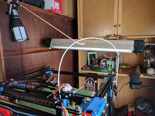
Michael K Johnson February 13, 2018 21:05
Huh. I tied mine loosely to the drag chain.
I’ve thought about putting the extruders above the cube for minimum Bowden length
Michael K Johnson March 02, 2018 07:22
The SD card isn’t reliably detected, and print from USB isn’t working either. The former seems to be faulty component, the latter firmware problem.
I’m removing and reinserting the SD card about 5 times each time I go to print. I’m not planning to debug this, instead I’m moving toward using a replicape ASAP.
Michael Westbay March 02, 2018 09:00
Since I wanted to use a BLTouch, I abandoned the controller it came with and went with a cheap GT-2560 A. It doesn’t have an SD card, and I couldn’t get the screen that came with the X5S to work with it.
But OctoPrint on a Raspberry Pi connected via USB works like a charm. And can be controlled from my desk on the other side of the room or monitored with the camera elsewhere in the house.
Michael K Johnson March 03, 2018 17:43
slic3r didn’t like the light but stiff Y carriage design I wanted to print, but I didn’t like how cura sliced it, so I used both FreeCAD and OpenSCAD to make a model that both versions of slic3r will slice. I haven’t printed this version yet because the printer has about 8 hours left to go printing euclidean and archimedean solids for my family mathematician. ☺
(I previously printed it sliced with cura in ABS, but I wasn’t satisfied with the print, and PLA+ is so much easier to print with…)
Michael K Johnson March 14, 2018 18:38
Finally finished this step of moving toward using a Replicape:
Michael K Johnson March 17, 2018 12:55
Upgraded firmware to 1.1.8 and it fixes a lot of my annoyances with the included firmware:
Michael K Johnson March 17, 2018 12:57
Using 1.1.8 and bed mesh leveling with 5 points each in X and Y, I found a distinctly not-flat bed:
echo:Mesh Bed Leveling:
echo: M420 S0 Z0.00
echo: G29 S3 X1 Y1 Z0.03000
echo: G29 S3 X2 Y1 Z-0.10000
echo: G29 S3 X3 Y1 Z-0.21000
echo: G29 S3 X4 Y1 Z-0.26000
echo: G29 S3 X5 Y1 Z-0.30000
echo: G29 S3 X1 Y2 Z0.17000
echo: G29 S3 X2 Y2 Z0.16000
echo: G29 S3 X3 Y2 Z0.16000
echo: G29 S3 X4 Y2 Z0.14000
echo: G29 S3 X5 Y2 Z0.01000
echo: G29 S3 X1 Y3 Z0.14000
echo: G29 S3 X2 Y3 Z-0.00000
echo: G29 S3 X3 Y3 Z-0.02000
echo: G29 S3 X4 Y3 Z0.04000
echo: G29 S3 X5 Y3 Z0.07000
echo: G29 S3 X1 Y4 Z0.10000
echo: G29 S3 X2 Y4 Z0.20000
echo: G29 S3 X3 Y4 Z0.26000
echo: G29 S3 X4 Y4 Z0.18000
echo: G29 S3 X5 Y4 Z0.11000
echo: G29 S3 X1 Y5 Z-0.26000
echo: G29 S3 X2 Y5 Z-0.15000
echo: G29 S3 X3 Y5 Z-0.21000
echo: G29 S3 X4 Y5 Z-0.25000
echo: G29 S3 X5 Y5 Z-0.25000
How much of that is the glass and how much the bed itself I don’t know, but total variance of over 0.5mm makes some of the printing problems I’ve had clearer. I’ve heard that mirrors are flatter and plan to switch soon.
Michael K Johnson March 17, 2018 20:47
For moving to replicape, which does not have dual connections for the Z stepper driver, I don’t want to slave E to Z; I’d like to leave E for a second extruder at some point. That leaves choice of parallel or serial. Serial makes a lot more sense to me because I’ll get full configured current through each stepper.
shows a nice harness technique visually, including suggested heatshrink tubing sizes to make things work well. I probably should have pulled the pins and put them into the empty JST header, but decided that just heat-shrinking them together is good enough for now.
Wiring Your Z Stepper Motors in Series
Michael K Johnson March 19, 2018 18:19
— I’m now thinking of completely replacing the bed, rather than trying to work around the warped bed with thicker glass with poor heat conduction.
I’m tired of trying to tram a warped bed. After realizing just how terribly …
Michael K Johnson March 22, 2018 06:32
My writeup on what I did to update my X5S to my own build of Marlin 1.1.8, which fixed bugs (like USB not working at all) and opened up new features (like manual bed leveling), is at
Michael K Johnson March 24, 2018 10:04
The X gantry started to wobble, which started wrecking prints. I replaced the M5x30 lower wheel bolt with a high-quality M5x45, thinking that I could use a zip-tie to provide tension on the back. It turned out that just using an M5x45 with a long shoulder was, at least for now, enough to resolve that wobble.
I haven’t yet come up with a good design for replacing the X gantry with something based on openbuilds gantry plates, which is a pity since they currently have a special on shipping. ☺
Michael K Johnson March 25, 2018 14:32
Y gantry movement is very stiff, even without belts installed. It would make sense if that were related to the occasional skipped steps I’m seeing. I hadn’t seen that since I increased the stepper motor current (though I don’t know what the reference is, so I don’t know to how much) but it happened today about 4 hours into a ~24hour print. Could have been worse, I guess!
The unsupported bolts through 4mm acrylic and a nylon pillar can’t be helping. The wheels are shedding plastic as they rub. Linear rail?
Michael K Johnson April 17, 2018 09:24
Linear rail and ATP-5 plate are both on order, and SSR and 120V Keenovo heater pad have arrived. Planning a kinematic mount for the new bed. Meanwhile, “thermal runaway detected” two prints in a row so either I have a bad thermistor or I need to PID tune my new merlin build—but if it’s PID tuning, why have I successfully put about a kilo of filament through on that build of Marlin? I also notice that I seem to have a fan mosfet failure on the board, so probably a sign that it’s time to try the replicape conversion again and hope it works better this time. I was kind of hoping to wait until I did the bed conversion so that I could get rid of the 12V power supply altogether, though.
Thinking of getting a bit radical with the linear rail and milling aluminum for gantry brackets and extruder carriage, instead of following the reprap “print everything in plastic” practice. For the gantry, that might let me make a light and simple T bracket that is stiff enough and much easier to disassemble.
Michael K Johnson April 18, 2018 18:45
Mark Rehorst put his kinematic mount adjustment screws into teflon as a thermal insulator for UMMD,¹ but I don’t believe in the need for that. The contact area is small, and steel has roughly a quarter of the thermal conductivity of aluminum generally. My plan is to use acorn nuts on the end of adjustment screws for the three-axis and two-axis constraints and a flattened screw for the single-axis constraint, rather than using ball-head screws that have to be adjusted through a hole or slot from the top. This way the adjustments can be from below the bed (as now) instead of requiring through-holes in the bed plate.
Mark put his three-axis and two-axis constraint chamfers on tabs across the middle of the plate. I’m planning to mill two chamfer sets on the bottom of the plate; one set using existing holes at the back of the printer for the three-axis and two-axis constraints, and one set at the middle of the plate that would require modifications to the bed structure in case the first ones are a problem. I’d rather do all possibly-needed milling before I attach the heater to the bed. The heated pad is 300x300mm on a ~333x333mm bed plate (I ordered 13.25” x 13.25” to give a little room), so I’ll have 16mm along the edge to add the chamfers. That’s more than enough, since the bed should expand by less than 1mm when it is heated!
Note that this proposed mechanism has no springs to protect in case of a extruder head crash. Don’t do that then? With a really flat surface and single-start Z screws, I should be able to avoid a head crash. I hope. [Edit: Actually, there’s no reason I couldn’t use the existing springs.]
¹ https://drmrehorst.blogspot.com/2017/07/ultra-megamax-dominator-3d-printer-bed.html
Michael K Johnson April 18, 2018 20:31
In my build of Marlin, I was using the default Ultimaker PID settings that were also in the source dump provided by GearBest for the printer:
M301 P22.20 I1.08 D114.00
After M303 C7 E0 S240:
…
Classic PID
Kp: 11.19 Ki: 0.57 Kd: 55.23
PID Autotune finished! Put the last Kp, Ki and Kd constants from below into Configuration.h
#define DEFAULT_Kp 11.19
#define DEFAULT_Ki 0.57
#define DEFAULT_Kd 55.23
So I added that to my Marlin fork at
Those PID values are close enough (within a factor of two) that I’d expect the to be OK. So I don’t think this is the key to “thermal runaway detected”, sadly. ☹
Michael K Johnson April 19, 2018 20:14
Finally found PEI in 13”x13” at — I looked without success on amazon and ebay several times before.
Michael K Johnson April 19, 2018 20:24
https://www.amazon.com/Soosee-Sheet-Printer-Surface-Adhesive/dp/B07B5YW6WN — same thing in 0.5mm
Michael K Johnson May 01, 2018 21:39
Linear rail arrived today. I finally realized, a bit late, that MGN12H is all M3. I have not enough short M3 bolts and no M3 T-nuts, only M4 and M5. I need M3x8 for mounting the rail to the 2020. There is 3.5mm of depth in the block for mounting screws. There’s no perfect combination of standard M3 screw length and US standard aluminum stock thickness for the block mounting screws. I’d like to leave 0.5mm allowance, so 5mm stock and M3x8 would be perfect. I think I’ll mill 1.35mm pockets in 1/4” plate around mounting holes.
My idea is to mount the rail to the top of the 2020 extrusion and replace all the motor and pulley mounts with properly-aligned mounts milled from aluminum stock. I’ll also probably replace the two-z-motor arrangement with a single z motor driving both Z rods with timing belt.
I now realize that the 450mm linear rail and the resulting re-design might mean I could have gone to a larger bed, 14x15” or maybe even 15x15” — but then the heater would have been more expensive and really this is already big enough.
Michael K Johnson May 12, 2018 22:19
I’ve stripped the printer back down to a frame with corner braces and empty vertical drag chain. I have started what will be essentially a custom build that shares a few components with the donor X5S.
Belt drive for Z is coming together. I’m so glad I never got around to cutting down the 500mm single-start 2mm lead 2mm pitch trapezoidal lead screws I bought; now I could use an extra few more centimeters conveniently.
I bought trapezoidal pillow blocks for the bottom to go roughly where the Z motors went. I drilled holes in the X rod plate matching the holes in the pillow blocks, then milled spacers out of 1”x½” stock to move the pillow blocks higher. I’m not 100% convinced that having trapezoidal pillow blocks at the top of travel is helpful; it feels like it might be over-constrained, so I’ll just leave them off for now; I can add them later. But the 500mm lead screws reach only to about 13.5mm below the bottom of the top 2020 extrusion, so if I do need pillow blocks at the top I’ll need to mill more spacers.
I’m putting 20 tooth 8mm inside diameter pulleys on the lead screws, and driving with a 40 tooth pulley on the stepper motor. I have a 570 tooth (1140mm) belt loop around it. I’m mounting the motor on a piece of ¼” plate that I’ll attach to the bottom of the lower 2020 extrusion, so the bottom of the motor will be aligned with the bottom of the extrusion. The spacers under the pillow blocks help everything line up so the belt will be planar. I plan to put an extra belt loosely around the base of the lead screw mechanism so if the belt ever breaks I can put a new one on without doing lots of disassembly.
Michael K Johnson May 14, 2018 20:10
I wrote: “Note that this proposed mechanism has no springs to protect in case of a extruder head crash. Don’t do that then? With a really flat surface and single-start Z screws, I should be able to avoid a head crash. I hope. [Edit: Actually, there’s no reason I couldn’t use the existing springs.]”
Having taken the printer apart, I now see that the six existing bed mounting holes are about 3.6mm wide; more play than I’d like for a kinematic mount with M3 screws and springs holding up the bed, but wider than will give me a good tap for M4 for a hard-fixed bed.
I want to avoid play side to side, and it would be nice to have some protection against damage from head crashes. A potential downside of the single-start trapezoidal lead screw in this instance is that the additional leverage means that I can’t count on stalling the stepper motor before I do damage.
Perhaps I should start by wrapping M3 screws in teflon tape as an ersatz bushing and thermal barrier. This would let me spring-mount the bed. If it works reasonably well, I could perhaps drill the holes out a bit wider and turn some small delrin bushings, or perhaps leave well enough alone. I don’t think I could turn 3mm ID 0.3mm thick bushings very well, though maybe it wouldn’t be so hard? I haven’t turned bushings less than 1mm thick so far, though. Might be a fun challenge?
Michael K Johnson May 16, 2018 18:35
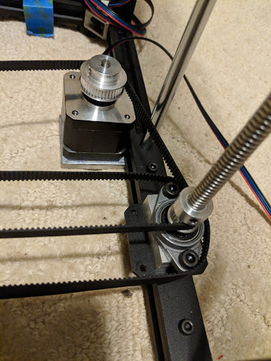
I assembled the Z stage movement. This is two 20-tooth pulleys on the single-start 500mm lead screws and a 40-tooth pulley on the stepper motor, with an 1140 mm 570 tooth 6mm wide GT2 belt around them. The motor is mounted on the inside of the frame, with the bottom of the motor aligned with the bottom of the frame. The motor is mounted on a flat piece of aluminum stock (1/4”) as wide as the motor and as long as the motor plus 20mm for the frame, and drilled appropriately to mount with t-nuts to the bottom of the frame and with the existing M3 screws to the motor (the same screws previously used to connect the motor to the motor plate).
The lead screws are set in trapezoidal pillow blocks mounted on top of 1/2” stock, held down to the frame with M5 screws, going through holes I drilled in the existing motor plates, and tied into the frame with M5 t-nuts.
The trapezoidal nuts were replaced with single-start nuts to match the new lead screw and the whole thing assembled back into the frame, with two belts in place as planned. I aligned the two sides where they bottomed out against the pillow blocks for a reasonable initial reference. I turned the screws quickly by stripping belt over the lead screw pulleys. When the Z carriage was near the bottom, I had substantial wobble at the unconstrained top. Therefore, I expect to machine two more 1/2” spacers and use pillow blocks at the top of the frame, like how it was initially shipped except with the spacers added. Longer lead screws might be a little more convenient but honestly I don’t think it needs to move higher. Apparently the lead screws are sufficiently flexible that this isn’t an overconstraint in practice.
Because I’m using 20 teeth on the lead screw and 40 on the motor, the move from 4-start to 1-start lead screw will only double instead of quadruple my steps per Z mm. Downward pressure on Z won’t make the bed creep. And a single stepper with a belt around the two lead screws will keep the two sides in sync. I like this better than the dual motor design.
Michael K Johnson May 16, 2018 18:39
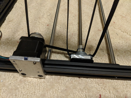
Side bottom view of motor mount plate, also showing 1/2” spacer below the lead screw. It’s also a better shot for seeing the extra belt, which is relatively snug around the trapezoidal pillow block mounting screws.
I did these parts in aluminum. The spacer could be plastic, but I would expect the motor mount eventually to creep under load if it were made from plastic.
Michael K Johnson May 16, 2018 18:45
I noticed when I was test-fitting that the X 2020 gantry (484 mm long) seems to just barely fit between the MGN12 trucks on the linear rail on top of the Y gantry 2020 top of the frame. But I haven’t mounted them, they were just sitting there loose, so I did the math…
Total X width is 530mm, so 510mm between centers of the Y gantry 2020. The MGN12 trucks are 27mm wide. There is half of each of the two trucks on either side of the centers, so 510mm between centers minus 27mm (two halves of the trucks) is 483 mm to fit a 484 mm extrusion.
Maybe I can mill the alignment brackets off by 0.5mm and make it fit? Alternatively, I can mill 0.5mm off the top 10mm of both top sides of the X gantry 2020 to make it just perfectly fit. I’ll have to think about that! ☺
Michael K Johnson May 19, 2018 17:54
I milled 0.5 mm off the top 10mm of both sides of the x gantry 2020. I milled alignment jigs for mounting the linear rail, and mounted it with all the M3x8 screws and t-nuts that didn’t interfere with existing screw heads in the 2020.
I mounted the X linear rail on the side of the x gantry extrusion. I haven’t yet decided what print head to hang off it first, but the nice thing is that I can do anything that matches the screw pattern of the MGN12 trucks, which should make it easy to change up.
I will have to mill spacers to add trapezoidal pillow blocks to the tops of the z screws because they wobble. Sadly 1/2” stock is about 1.5mm too thick, so I’ll have to face them.
Then I’ll have to mill T shapes to attach the Y trucks to the X gantry 2020. That should be easy enough. But if they aren’t perfectly square, my prints will be skewed.
Michael K Johnson May 21, 2018 08:31
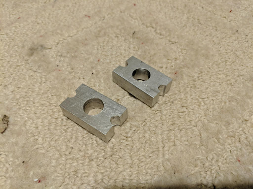
I milled the spacers for the z lead screw tops, for mounting the pillow blocks. I made them just like the bottom blocks, then realized I couldn’t get the t-nuts into the slot in the 2020 without being able to drop them at least part way down over the lead screws. Rather than worry about how deep a pocket to mill, I just drilled all the way through the middle. A pocket would have made installation a tiny bit easier, maybe.
This is not a precision part, and it is not under significant stress. The hole and half holes are intentionally oversized for easy fit. If I hadn’t already been set up to mill these pieces, printing them would have been appropriate. The half holes could easily be normal through holes in a slightly longer part.
Due to the flexibility of the lead screw, these are not actually an over-constraint. They solve the problem of free end whipping when the bed is at the lower travel extent, and reduce vibration/chatter throughout travel range.
Because I removed 1.5mm from the face, M5x25 screws were about 1.5mm too long. So I put three washers under the screw heads. Good thing this isn’t a precision part!
Michael K Johnson June 16, 2018 22:46
No pictures tonight, but… I milled some prototype X gantry holders. I used .25” aluminum, 26mm x 100mm, which was just enough to try out the movement and not enough to mount pulleys on for driving the movement, but it let me experiment with a design to keep everything square.
I milled a pocket in the bottom 1mm deep. It was 2mm from one long edge, and 20mm wide, leaving 4mm on the other edge. The pocket went all the way to the edge at one side and to 26mm from the other edge. The pocket fits the 2020 extrusion to hold in straight. In the last 27mm, I drilled 4 3mm holes, 20mm on centers, to fit the M3 screws needed for the MGN12H carriages, and I pocketed 1.25mm deep around each of those 4 mounting screw locations so that M3x8 screws would be the right depth to mount to the carriage trucks. I drilled 3mm holes centered 10mm in from each edge of the pocket and 8-10mm from the ends of the pockets. I used M3x8 screws and M3 t-nuts to mount to the X 2020. I made two of these, in mirror image, for left and right mounts. The 2mm edge of the pocket is toward the front, and is small to avoid interference with the front-mounted linear carriage on the X 2020. There is more room on the back, thus 4mm. The 2mm and 4mm edges hold the 2020 extrusion square.
Mistakes I made included using a chuck instead of a collet to hold the center drill for starting holes in the first of the two holders. This made the holes insufficiently precise and one of the four just doesn’t match up, even after drilling out with a 3.2mm oversize bit. Using a 3/16 collet and a #2 center drill to start holes for the second holder was more precise. (I know better than to have tried the chuck…)
It runs square. It’s a little bit stiff, and it’s stiffer toward the back, which indicates that the linear rail isn’t quite straight, even installed with the jigs I made. Or maybe that the frame isn’t quite as square as I think. That will take some investigation.
The real holders will have to be larger and have mounting built in for pulleys. I’ll probably use two pulley stacks with vertically-aligned belts aligned with the front of the extruder carriage truck. Alternatively, I could just use the existing holders and screw some square tube on top to hold the pulley stacks. I’ll see.
Michael K Johnson June 21, 2018 22:39
A whole album of pictures of the next (final if I’m lucky) revision of the gantry mounting plates, plus discussion.
I’m slowly building a rather different printer on top of the skeleton of my T…
Michael K Johnson July 05, 2018 22:30
I milled some 1.5” square tube (more scrapyard special!) with 1/8” walls, lining up 5mm holes for M5x45 bolts through into the M5-tapped holes in the gantry plates. I did two in mirror image, one for each side. They sit on top of the screw heads for the gantry plates, which isn’t obviously optimal; maybe I should instead use some spacers or bushings. But since they contact only three screw heads and three points determine a plane, maybe this is actually the best arrangement. Don’t fix what ain’t broke?
I noticed, finally, that I had lost track of where I should drill the tapped holes in the gantry plates, and ended up with the belts lined up with the bottom of the front-mounted linear rail carriage instead of with the ball bearing slot in the linear rail as I had originally intended to do. Doesn’t really matter, probably. It will just change my carriage design a little bit, and since I haven’t started that design it’s a distinction without a difference.
I haven’t yet added bushings/spacers to the M5 bolts to hold the idlers in place. The bottom right 20T idler in this picture is just there in place of a bushing I will add later. I just needed to test out the height for now.
The way I’ve stacked this up moves the belt path much higher than it was on the printer as shipped. I’m thinking of mounting the front corner idlers inside 2” square tube, which would require buying 55mm M5 bolts. An alternative would be just using 1/2” aluminum pieces which would not require support at the top, perhaps. I also need to think about machining new motor mounts.
To drill the bolt holes more precisely, while I did center-drill the holes with a collet-mounted center bit to start the holes, I also used a 5mm collet to hold the 5mm drill bit instead of a chuck. The holes lined up very nicely!

Michael K Johnson September 03, 2018 22:21
I occasionally make progress on this project. A month or more ago, I added bushings where they are missing in the picture above. I reused some of the bushings that shipped with the printer, then added a few more in custom lengths. A few weeks ago I milled out some thicker aluminum blocks as spacers for mounting the motors and some inch-thick blocks off the front corners for mounting corner pulleys. The thick blocks mean, I hope, that I don’t need to support the pulley bolts top and bottom; I’ll see how well that works. Because of the square tube holding the pulleys on the Y carriage, I had to put the front outside pulleys well outside the original printer envelope to keep the belt out of the way event when the carriage is at full back Y travel. The alternative would have been yet another idler.
Yesterday and today I milled a single-extruder bowden extruder carriage with belt clamps. I used a 45⁰ chamfer bit to score the belt-holding faces with .2mm lines 1mm apart all across the face. After loosely installing the belt, I tightened the screw part way, grabbed the belts with pliers, and pulled tight. They stayed tight while I screwed down the clamp. What I have now is still the stiff steel-core cable that shipped with the printer, but I plan to replace with glass-core because it’s pretty stiff going around all those pulleys… But both belts pluck about the same note so they are approximately equivalently tight, and the XCR3D XCR-BP6 mounts tight; it’s not going anywhere.
The belts are a bit too far apart in height because I used an M5 screw for the clamp. In retrospect, an M4 might have been a better idea, and I have more of those handy anyway. The larger screw will create a bit of angular deviation at the extremes, but probably not enough to measure.
I’m also planning to make a carriage for direct feed with the aluminum titan clone. There are three known problems with those: the hobbed gear is installed in the drive gear upside down so it doesn’t align with the filament correctly (fixable by buying the original), it doesn’t have a filament constraint (fixable by making and installing one) and it doesn’t use a bearing around the motor shaft used as a pivot for the arm (I hope fixable by milling it out and installing MR58 bearings).
Sorry for the ugly picture.
Michael K Johnson September 15, 2018 09:49
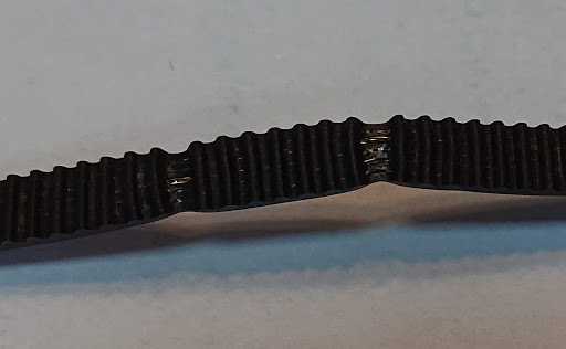
I think the 2mm pitch on this timing belt is a little off in some places… ;)
I bought fiberglass core belt to replace the steel core that shipped with the printer. I’ll see how that works.
Imported from Google+ — content and formatting may not be reliable