3D printed bearing blocks
I designed new bearing blocks for bronze bearings for my old hictop i3 clone. It had very loose SCS8UU pillow block bearings for the bed and I could see the bed wobble as it moved. It didn’t make for very precise prints. I previously put bronze bearings into printed SCS8UU pillow blocks but they kept falling out and ruining prints, so I had to get creative!
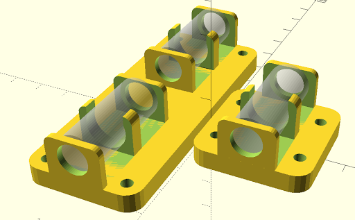
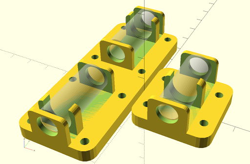
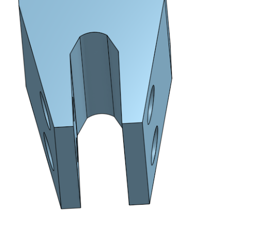
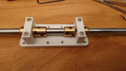
The bearings just slide into the three clips between the rings.
This design would probably work for the print head too by just adjusting the inter-block distance (one of the top parameters), but that’s not obviously giving me trouble and I don’t want to disassemble that part of the printer right now. So for now I consider it a set of Y axis blocks.
This should work with any printer that uses three SCS8UU pillow blocks, two co-linear on one side, and one on the other, by measuring the length and outer diameter of the bronze bearings and the distance between the two co-linear pillow blocks with a set of calipers. You will really want to use a tap to thread the holes; if you don’t do that, you’ll want to print a wider hole to reduce the self-tapping effort for the M4 screws. I tapped mine with a spiral tap, so I won’t be any help on hole sizes when not using a tap.
It’s sufficiently parameterized that it should work for other sizes of rail and bearing pretty well. I tried to set it up for the thingiverse customizer but it seems to be ignoring that.
My first design was over-constrained and had too much friction. This design is working much better so far. Fingers crossed!
https://www.thingiverse.com/thing:2993926
https://github.com/johnsonm/y-bushing-blocks
HICTOP i3 clone Y-axis bronze bushing holder by mcdanlj
Michael K Johnson July 07, 2018 21:48
Would probably want to add zip-tie channels to use this oriented to hold the print carriage, though it’s definitely not necessary for the bed as far as I can tell.
I’m using the 30mm graphite bearings, but I’m wondering whether the 15mm oil impregnated sintered bronze bearings would be better. Not sure it’s worth taking the printer apart right now to experiment. :)
Michael K Johnson July 08, 2018 22:27
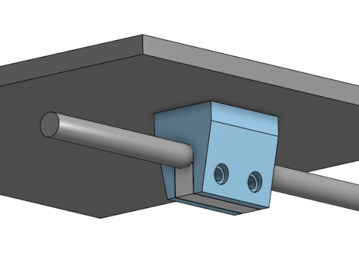
Here’s a screenshot showing how the bushings are mounted.
Preston Bannister July 10, 2018 15:00
Have to admit, tempted just use a printed-plastic bushing, directly on rail, if/when I re-build my i3 clone. The solid printed plastic bearing for the X motion on my TronXY X5S is … just working. Have a few hundred hours of printing, and no detectable play.
Would be simpler, if it works as well.
Michael K Johnson July 10, 2018 16:54
That was the first thing I tried and it sure didn’t work for me. Milled igus / delrin / acetal might be ok too.
Preston Bannister July 10, 2018 21:10
+Michael K Johnson What did you try, and what did not work?
The loads are so light in this use, the ridiculous printed plastic bearings seem to work quite well. At least in my example.
Starting to think that I want a couple of smaller / slower printers just to crank out smaller parts. Some refactoring of the i3 / Printrbot design family, made as simple as possible. Use printed parts to simplify the design. (What is +Brook Drumm up to now?)
Michael K Johnson July 10, 2018 21:28
I printed out at least five different patterns for bushings, and they were either sloppier than the ones that came with the printer, or they stuck. Might have been a bit of toolmakers paradox at work in that the lack of precision in the bearings I used while printing the bushings made the bushings fail in precision too.
Not saying it can’t work, just didn’t work for me, and this design is specifically intended to avoid overconstraint even in the case of somewhat imprecise printing, so that it is useable even with imperfect calibration, or filament that doesn’t shrink identically in each dimension, or various printing artifacts, taking advantage of the strengths of self-lubricating bushings which are not super expensive and so make sense to me as “vitamins”.
Michael K Johnson July 18, 2018 18:52
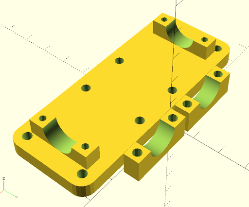
I moved the clips out from the center (by a parametric factor, natch) on the long holder, and added holes so that the long style can be printed twice and installed on both sides. No idea yet whether that’s a good idea! While this image shows the 30mm variant, I’ll probably switch to the shorter variant with oil-impregnated sintered bronze for the next iteration that I actually print.
Preston Bannister July 18, 2018 19:37
If I follow, moving out the clips might reduce your print area in Y. Have not seen your exact printer.
As to getting exact fit on the solid bearing, I used hand clamps to press the bearing tightly against the rail and a bolt to lock into position (not to add pressure). Broke the slider free by hand, after which it moved without trouble.
Michael K Johnson July 18, 2018 19:43
No, the clips fit within the original footprint. I just moved them from the centers of the bushings to near the ends of the bushings, without any change to the outside dimensions. This more tightly constrains the bed against Z-yaw without increasing the number of the constraints or the need for precision when printing. Feel free to look at the changes in GitHub to more clearly see what I did — you can set the offset factor to 0.5 and it will be the original arrangement.
Michael K Johnson July 21, 2018 14:18
I decided to test the 15mm self-lubricating bearings I have instead of the 30mm graphite ones. I tried reducing the diameter of the through-holes for the rail to 8.5mm and discovered that there wasn’t enough clearance, so that the rail stuck. On the other hand, it actually was a nice tight fit for the rail without bushings at all.
So I have modified the model to include a channel in the base along the length of the bushing to allow some measurement error / variance in size, and am printing it using the bushingless holders. I’ll see how that goes. It’s the first time I’ve had the bed move smoothly in printed bushings, and this time I wasn’t even trying to accomplish that!
Preston Bannister July 21, 2018 22:12
Know you are set on your present path, but wanted to make clear how I would go about a printed-plastic bearing for Y motion. Words are less clear than pictures, in this case.
Preston Bannister July 21, 2018 22:12
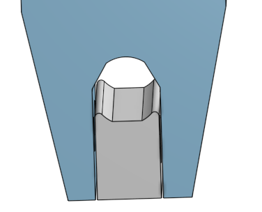
Preston Bannister July 21, 2018 22:12
Michael K Johnson July 21, 2018 22:38
Oh, that’s a nice design! Definitely better than the bearing blocks I found when I looked a few years ago. I’ll iterate on mine for now; I’m having fun, but a design that lets you remove/replace without re-tramming is a particularly nice feature of your approach.
I could hybridize my base with your saddle and block to get the fit to my frog but add easy removal and replacement.
I think I would print it in PLA instead of PLA+ because I think straight PLA would have lower static friction. My prints from version I printed where I inadvertently tested my design for use without bearings have some artifacts that seem primarily associated with stiction.
Preston Bannister July 21, 2018 23:44
+Michael K Johnson Thanks. Again, I am not inventing anything here, just recalling decades old designs I saw long ago, and translating forward into something we can print out of plastic.
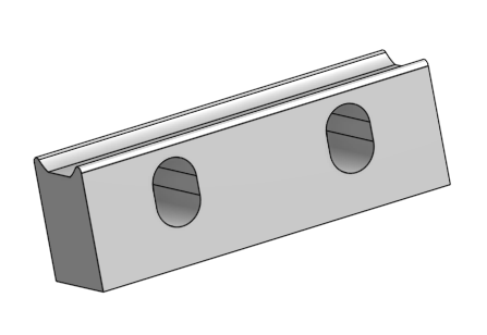
The lower “clamp” should protrude slightly below, so should be able to press (hand clamps?) firmly against the rod, then lock in place with through-bolts. First movement would need some force, but “sand” the plastic surface to tolerance tighter than we can print.
Michael K Johnson July 22, 2018 09:57
I’m thinking of ordering some igus drylin bushings. The brass bushings I found have horrible tolerances, which is causing me trouble. And it might be that sintered bronze won’t wick oil properly on a printer anyway.
Michael K Johnson July 22, 2018 20:38
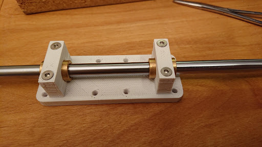
I still like the idea of bushings as “vitamins” from a materials standpoint, but the idea of using a clamp instead of a clip to hold the bushings I like. I ordered IGUS drylin bushings but can test with brass I already have in the meantime, and can swap out without detaching the base from the bed. The holes in the clamp halves attached to the base are sized to tap for M3 (blind tap, so even more important to use spiral tap to clear the plastic), and the free clamp halves are designed for M3 flat head screws. I’ll print two of these sets and see how this design works.
Michael K Johnson July 23, 2018 20:26
With 15mm bushings, it’s too stiff, even though I tightened it with the rod inserted through the bushings.
Michael K Johnson July 23, 2018 20:27
The 30mm bushings slide much more easily.
Preston Bannister July 23, 2018 20:51
+Michael K Johnson Huh. Are the printed parts maybe just very slightly not-straight, and the longer bearings have leverage to self-align better?
I would try putting a very slight taper to the hole, so the very center is tighter than the ends of each clamp, so the exact alignment can “float” slightly.
In fact, as a check, might go all the way to a 1mm inset “waist”, just to see what happens.
Preston Bannister July 23, 2018 20:53
… and if that works, will have to update my all-plastic design. :)
Michael K Johnson July 23, 2018 20:58
+Preston Bannister I’m fairly confident that they have some slight trapezoidal error from stiction—I’m still running on the accidental test of printed plastic bearings. A 1mm waist is indeed exactly what I was thinking about for an alternative if running with the 30mm brass/graphite bushings doesn’t solve the problem. But first, I’m planning to see how easily they run with the graphite/brass bushings, and probably print new sets with better bearings to compare. By then the drylin bearings should have arrived and I can test them as well. I can also compare to putting the drylin bushings into pillow blocks.
Michael K Johnson July 23, 2018 22:43
Yup. About 1° trapezoidal error. I think the printer has a design flaw making it tricky to keep square. I don’t think stiction is the main culprit here.
Michael K Johnson July 24, 2018 21:14
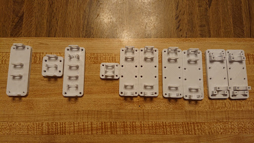
Five iterations that I’m not using. First iteration trapped bushings between end caps. Second changed to clips. Third moved clips to end. Fourth fiddled with clearances. Fifth had screw-on brackets too small and too much clearance inside. Sixth iteration installed but a bit late to test printing with tonight.
Preston Bannister July 25, 2018 12:54
+Michael K Johnson Heh. Iteration. At the end of the day, that might be biggest deal about 3D printing. You would not go through as many iterations, if you had to fabricate by hand. That means you get to better designs, more quickly, and likely your design skills improve. Then that better-design is easily replicated by anyone sufficiently skilled in using a 3D printer.
That snowball effect should be the main story of 3D printing.
Michael K Johnson July 25, 2018 18:35
Truth. I can spend as much time with lathe or mill making a part as I do in openscad designing a part to print… Though with substantial differences in precision!
Preston Bannister July 25, 2018 19:04
+Michael K Johnson Heh. Read your comment two ways, though expect you meant the first.
For a simple part, with a single or few critical dimensions, pretty sure manual fabrication with a lathe or mill is a lot more precise.
For a more complex part, with a chained series of interrelated critical dimensions, manual fabrication would be a nightmare. For a printed part, chained tolerances do not cost near so much. If we can design for looser tolerances, we can design more complex things than practical with manual fabrication.
And replication is almost free.
As a profession, we have several decades of designs meant for old forms of fabrication. Calls for some refactoring of how we design.
Makes for an entertaining topic. :)
Preston Bannister July 29, 2018 20:18
OK, printing the silly plastic bushing, to see if they work. No immediate plans to put on my i3 clone (the existing bearings seem OK). Found a (mostly) smooth rod with which to test.
Was watching a video, and at this point:
… he shows a bearing design not suited for 3D printing. Was more(!!) than a bit annoyed. The design is not suited for a 3D printer. We should use designs suited to the materials and method of manufacture.
BTW, my X5S is sitting on a desk I build in 1981, as a poor college student, with a handsaw, electric drill, and limited skill. Bit battered, nothing fancy, but solid strong and true. Designed something I could fabricate easily, and it worked.
Let you know in a few hours…
Michael K Johnson August 06, 2018 21:26
Sorry, just saw that google had “helpfully” marked your comment as spam without notifying me; I just fixed that. Now I know what set off your separate thread!
My printers sit on a desk that I designed and built shortly after I graduated from college, with a saw, electric drill, and limited skill. ☺
I’ve been thinking about my trapezoidal error problem. I think that it is more than the printer being out of square. I think that I need to lower X acceleration and jerk as well as Y acceleration and jerk. If that is the real source of apparent trapezoidal error, I should print the clips larger rather than smaller to reduce the impact.
Imported from Google+ — content and formatting may not be reliable