Making thermal isolating blocks for a kinematic mount
The Digital Dentist (Mark Rehorst)’s UMMD posts convinced me that I want a kinematic mount on my corexy printer I’m rebuilding from the skeleton of the piece of junk tronxy x5s I bought early last year. He recently blogged about some of the changes he as made, which included more stable thermal isolating mounting blocks.
I’m not not 100% certain that the thermal isolating blocks really matter for the constraining mounts; a steel screw conducts heat much less than the aluminum bed, and the amount of metal touching between the adjustable head and the bed is very small, further reducing conducting heat away from the bed. So for my first attempt, I just used M4 screws through the rail that came with my tronxy x5s, capped with acorn nuts on the end to interface with the bed. However, the longest screws I could find; M4x25, weren’t quite long enough to allow the bed to reach the hot end with the carriage I had designed, and the long unsupported screw through a short threaded section was not stiff enough; the bed moved too easily.
[Turns out, I missed the main point of the block, which is that cutting threads leaves too much clearance and a loose fit; thermal isolation is only secondary.]
Back to the drawing board. Regardless of whether PTFE is necessary for insulation, it’s a good material to make the mounts out of.
I cut two 2020 v-slot extrusion to replace the rails, the same length as the rails. I drilled 5mm holes through the middle of the v-slot at the three locations where I had previously tapped the thin solid square rod for my first experiment to match the features I had milled in my cast aluminum bed. I mounted that on the printer to replace the rails that came with the printer.
I took a block of 2” x 4” PTFE stock, cut off about 30mm of it on a band saw, and then cut it into rough thirds. Making the second cut was a challenge because the clamp on the saw wasn’t close enough to the blade, so I stacked some 1-2-3 blocks, and put the first cut-off piece at the back of the blocks, so that I could make the second cut:
I used a 45⁰ insert end mill with ground inserts to face all the blocks to identical dimensions. (Milling PTFE makes a mess…)
Then I made these blocks:
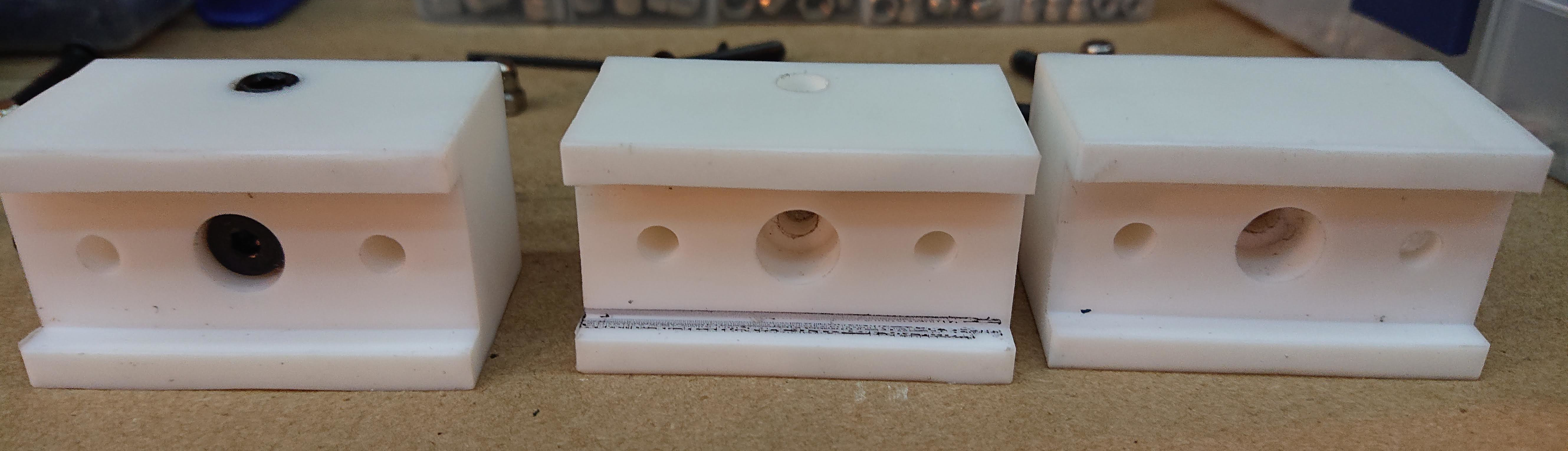
I milled a 20mm wide slot, 4mm deep, along the length of one set of identical sides. I put all three blocks in the vice and milled them all at once. I used a 12mm end mill, making it easy to dial in exactly 20mm by moving ±4mm on the DRO. Then I drilled the middle of that slot on each block for M5 with a 4.5mm bit, and plunge-milled with the 12mm end mill to leave 16mm of hole to thread M5. Then I tapped the hole with an M5 tap. (If I were doing it again, I would tap it almost but not quite all the way through, for a tighter fit.) I think of PTFE as really slippery and low-friction, so I was quite surprised how hot my mills and drills got while working in the PTFE! This was my first experience milling PTFE.
[Update: TDD said:
I didn’t tap the holes for the leveling screws. The steel screws will roll their own threads in the soft PTFE and the result will be a tighter grip on the screws than if the holes are tapped. You won’t need a grub screw to hold the adjustment.
If I re-do this, I’ll follow his advice and skip threading the M5 hole in the center of the block, and skip the M8 grub screw, simplifying the process and improving the result.]
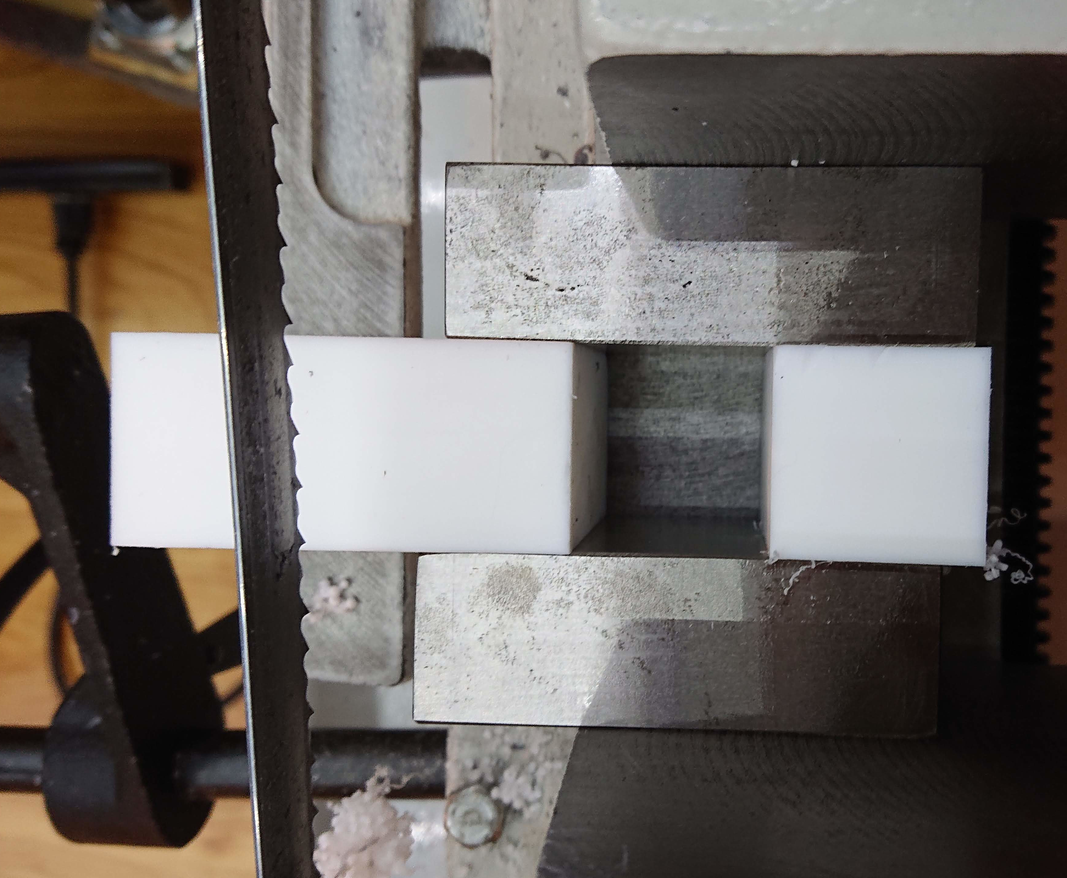
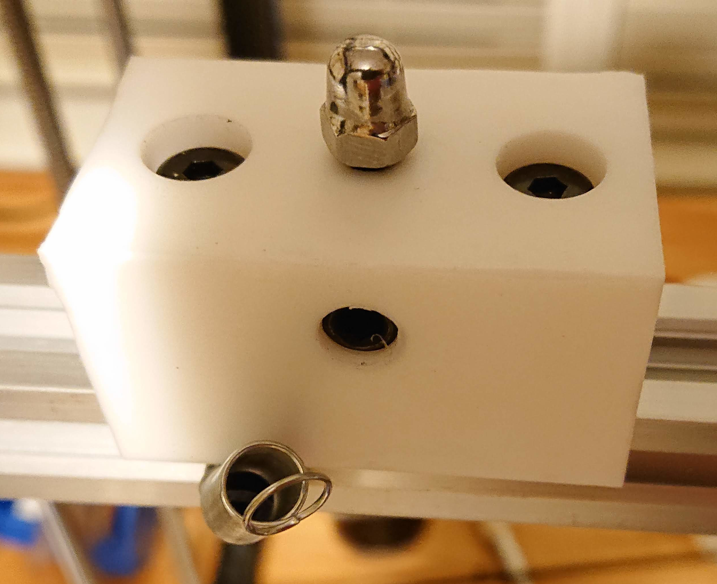
From the opposite face, I drilled 5mm holes on either side of the center, and plunge-milled them to leave 4mm of bolt protruding below the slot to engage a M5 T-nuts.
From the side, I drilled 6.5mm to the threaded portion of the M5 threaded hole in the middle of the block, then tapped M8 for a set screw. [Don’t do this; see above.]
I put a flat face on the top of one acorn nut using the lathe. I’m not sure this was necessary or even a good idea, but I wanted to avoid wear. And to play with the lathe. I achieved at least one of those objectives.
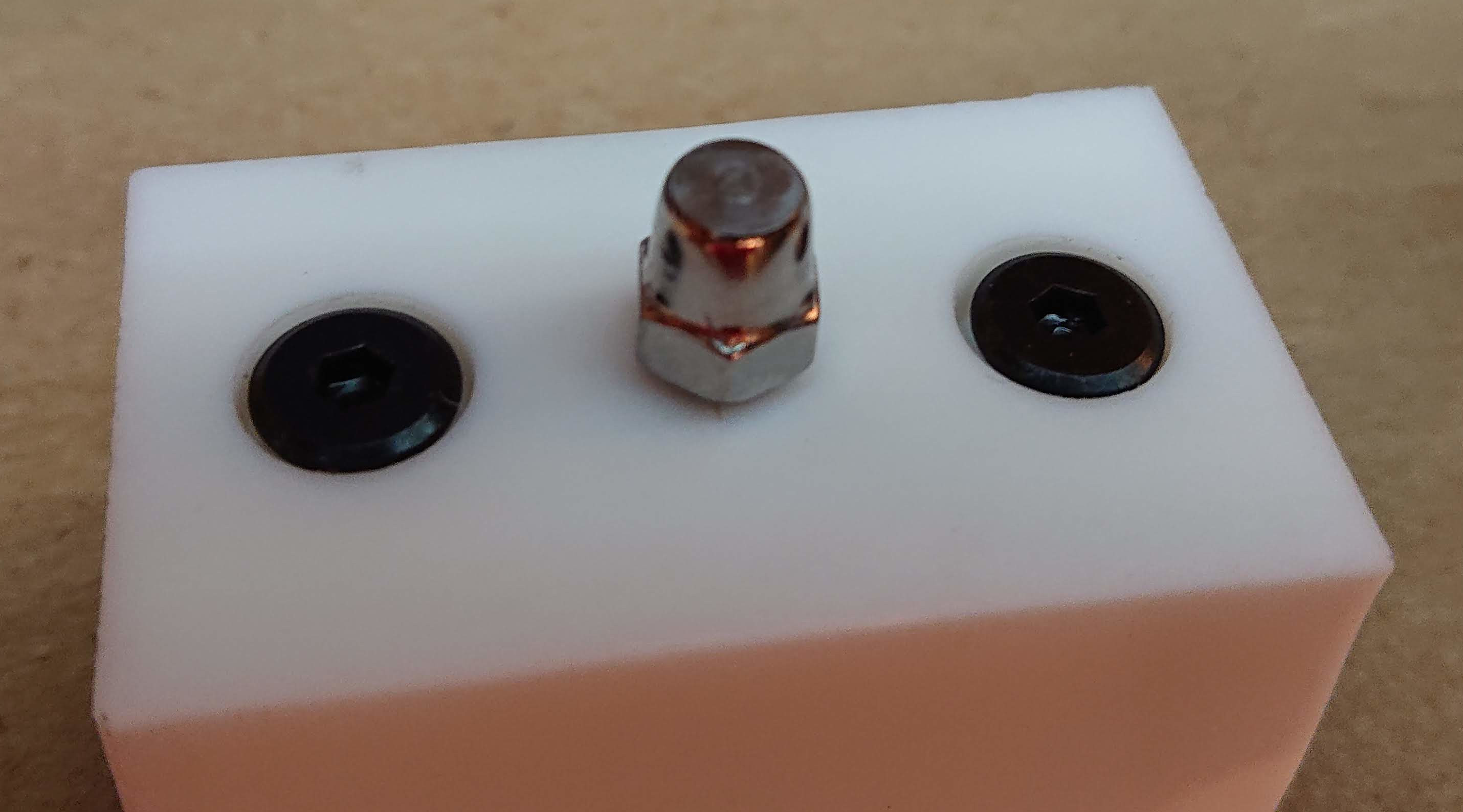
I threaded a low-profile M5 bolt from the channel side, and tightened an acorn nut on each M5 bolt. One of them was the flattened one, the other two were normal acorn nuts to engage the hole and slot for the kinematic mount.
I installed low-profile M5 bolts in the opposite direction and loosely put M5 T-nuts on the ends protruding into the channel.
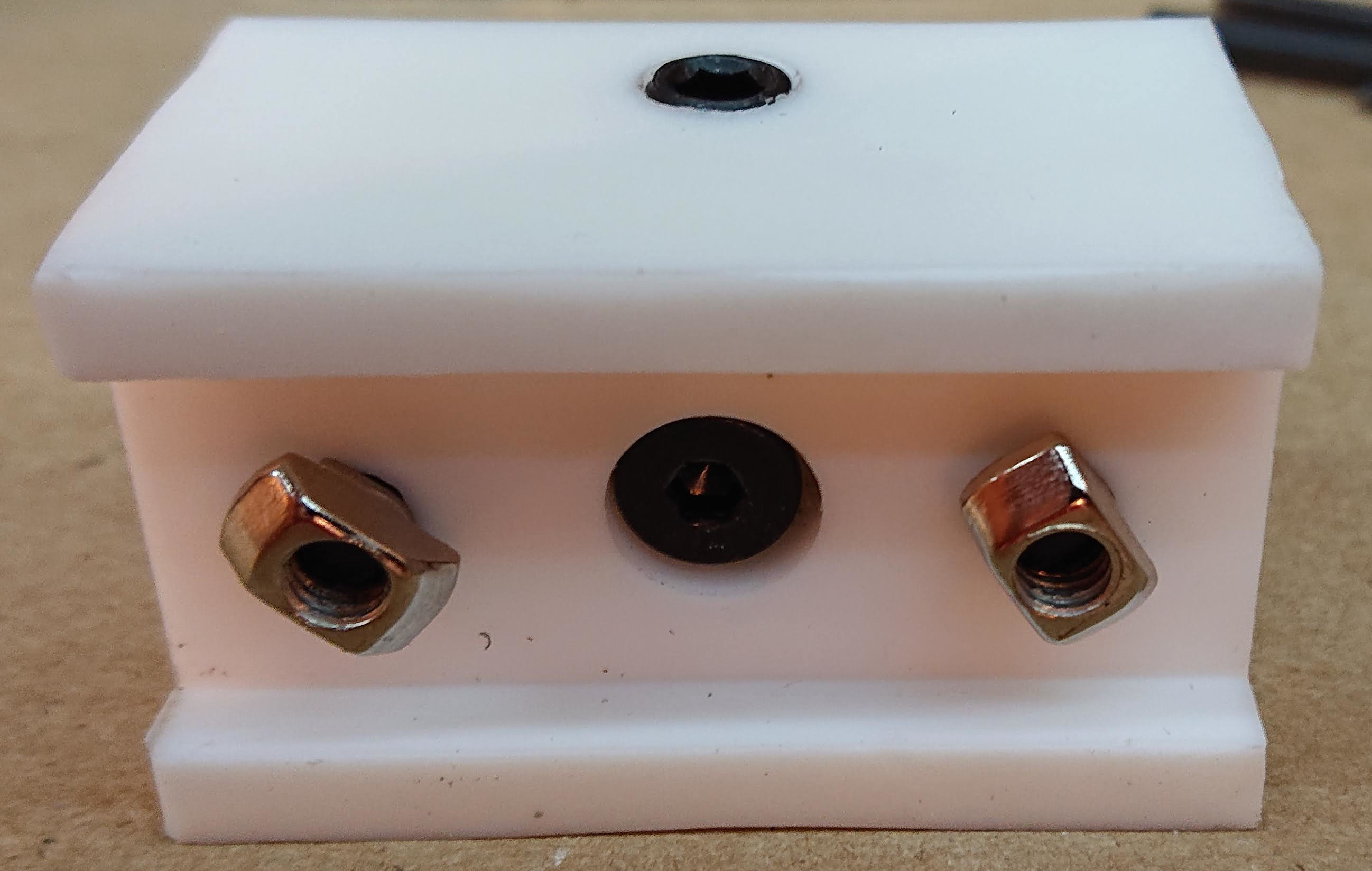
I installed M8 grub screws loosely in the side.
Holding an allen wrench through the holes in the 2020 extrusion, I mounted each mounting block in place and tightened the bolts, making sure that the T-nuts engaged in the 2020 slots properly. (The bed will be brought into tram using allen wrench through the holes in the 2020, and then the M8 grub screw will lock the height adjustment in place. [You won’t need the M8 grub screw])
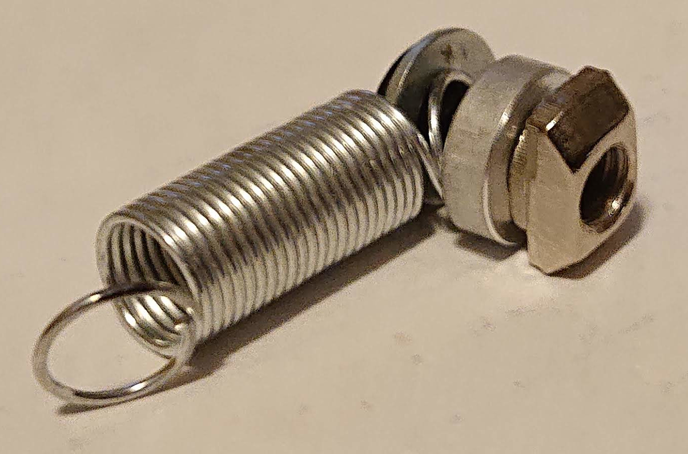
I used springs from the bed to the 2020 to hold the bed firmly in place.
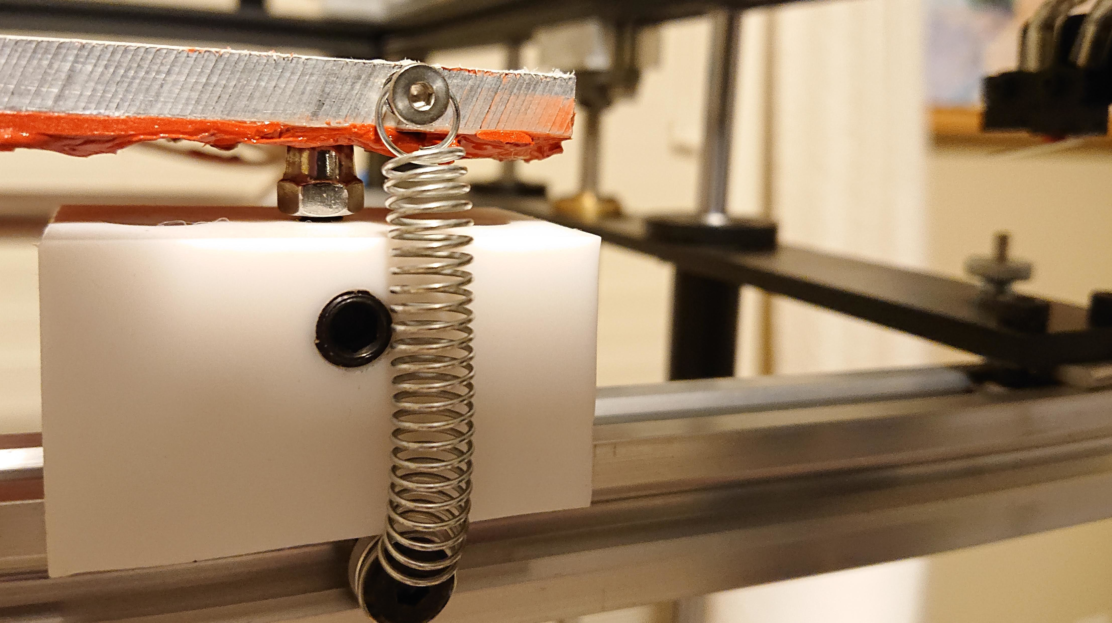
The stackup to hold the springs to the extrusion is an M5x8 low-profile screw through a washer, the spring loop, then a 3mm spacer, into an M5 T-nut.
No prints. I did this experimentally, trying things out as I went, and working with the dimensions of what I had to hand for PTFE, bolts, nuts, grub screws, springs, spacers, washers, and such.
Now, the bed reaches up to the extruder nozzle and is definitely more stable than being on the top of long M4 screws in necessarily slightly loose threads in a narrow square rod. A definite improvement.
Comment at Maker Forums