Replacing treadmill motor bearings
My treadmill drive belt was wearing out, so I found out what kind of belt it was and replaced it.
The deck belt slipped a little bit when I walked, so I tightend the drive belt a good bit. That was great for the first 30 minutes or so, until I heard the grinding noise of a dying bearing. That’s how I realized I had over-tightened the belt.
I’ve really been missing my treadmill time over the past two weeks. But now it’s back together, hopefully with higher quality bearings, and tightened only just until the deck belt stopped slipping while I walked.
Here’s a rebuild log in pictures, along with some things I learned.
Recommended tools if you happen to have exatly the same motor:
- Non-marring hammer, dead-blow recommended
- 14mm box-end wrench
- 10mm socket
- #2 Philips screw driver
- flat screw driver
- machinists’ square
- A bearing puller or set — don’t mangle a pulley puller like I did.
- 3/4” (or 18-19mm ID) plastic pipe
- 3mm hex wrench
Recommended parts:
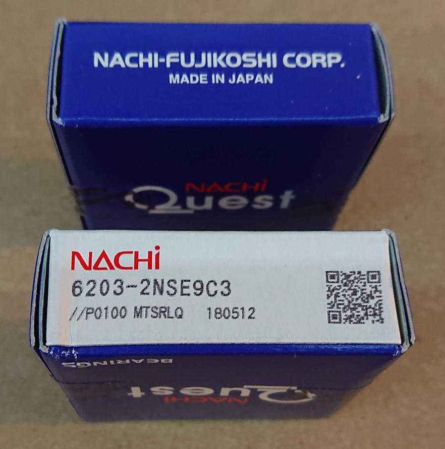
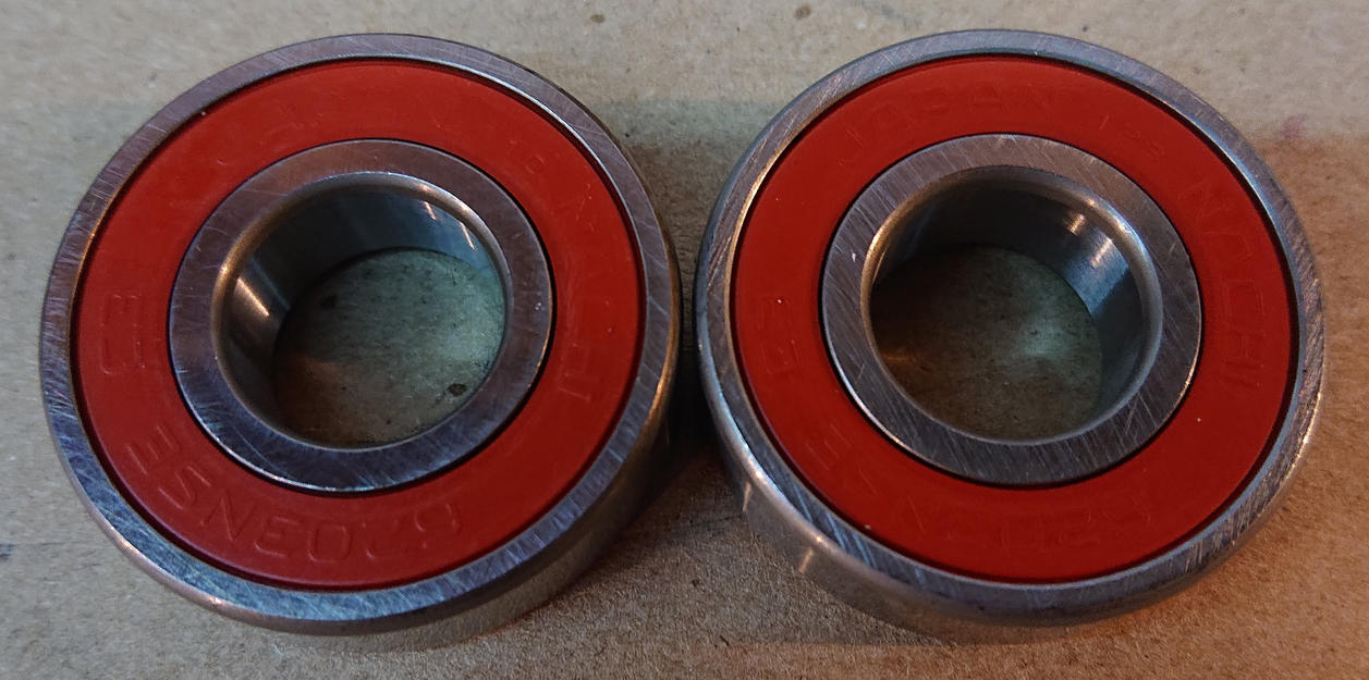
- 2 6203 sealed bearings, such as these Nachi C3 bearings — cheap bearings are about $1 each, but you probably don’t want to re-do this project repeatedly.
- 1 M4x8 hex socket screw
I ordered 6203 bearings; a common kind. I didn’t want to do this again too soon, so I ordered Nachi bearings from Japan that are supposed to be high quality. I also ordered C3 bearings that are a little bit looser than normal, as they are supposed to better tolerate the heat that can build up when I run my treadmill for a long time. They are rated for way faster than my treadmill motor is rated for!
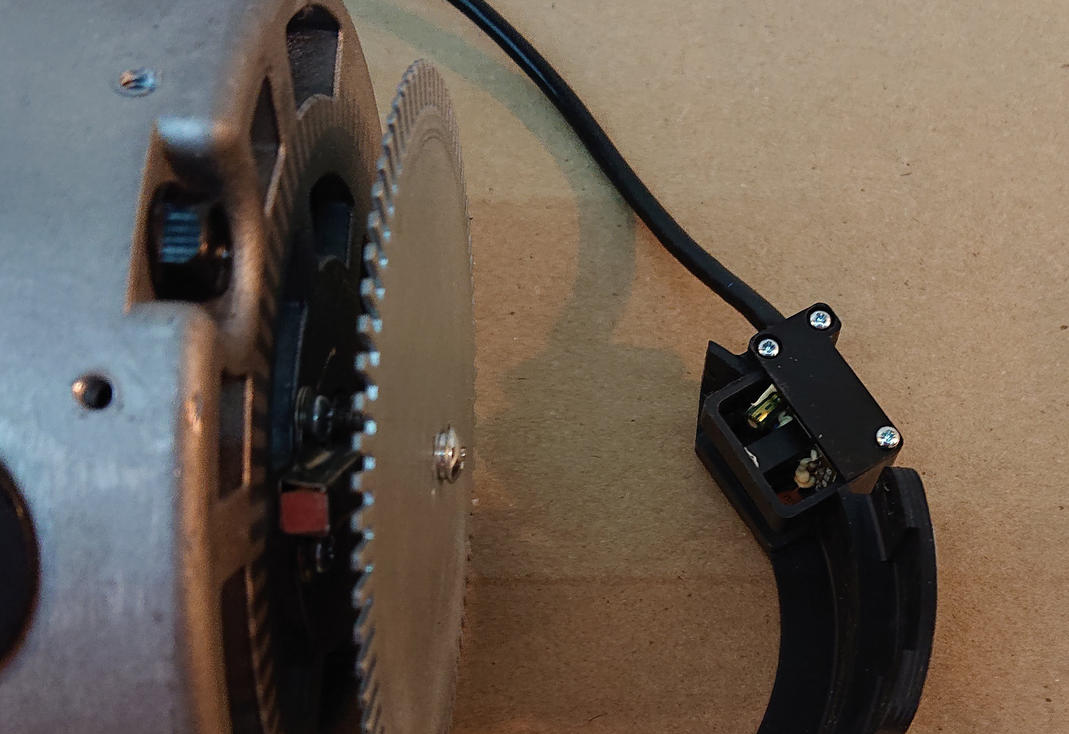
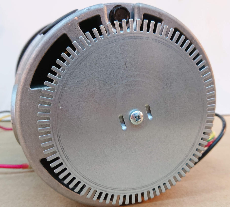
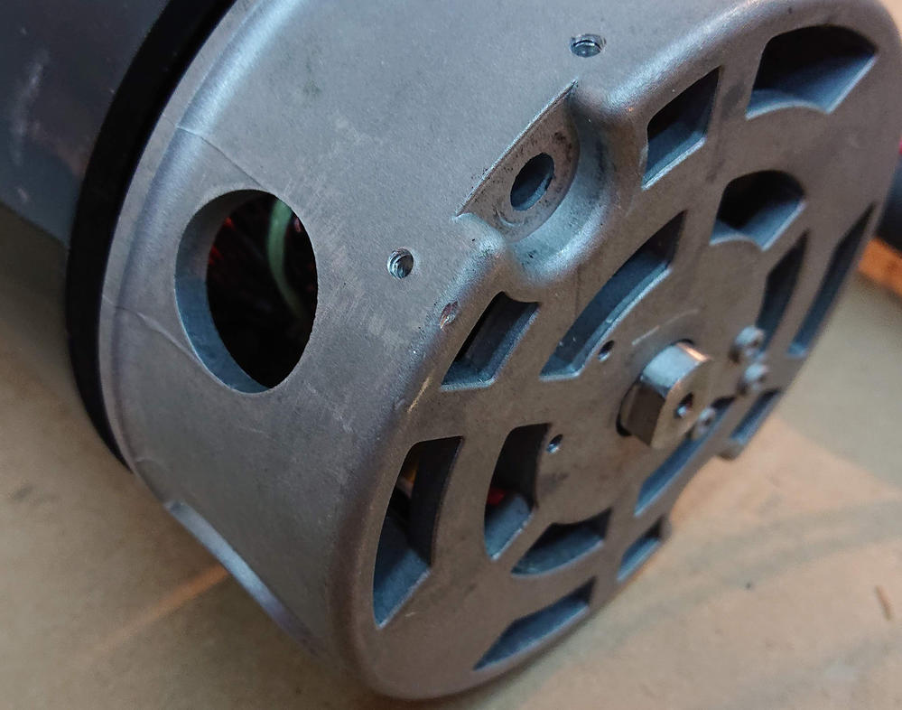
The first step was to remove the encoder. This is what the motor controller in the treadmill uses to keep accurate track of speed. Every time on of the little fingers on the encoder wheel goes by the sensor, the control board reads a pulse. There are only two screws holding it on. They were a bit tight.
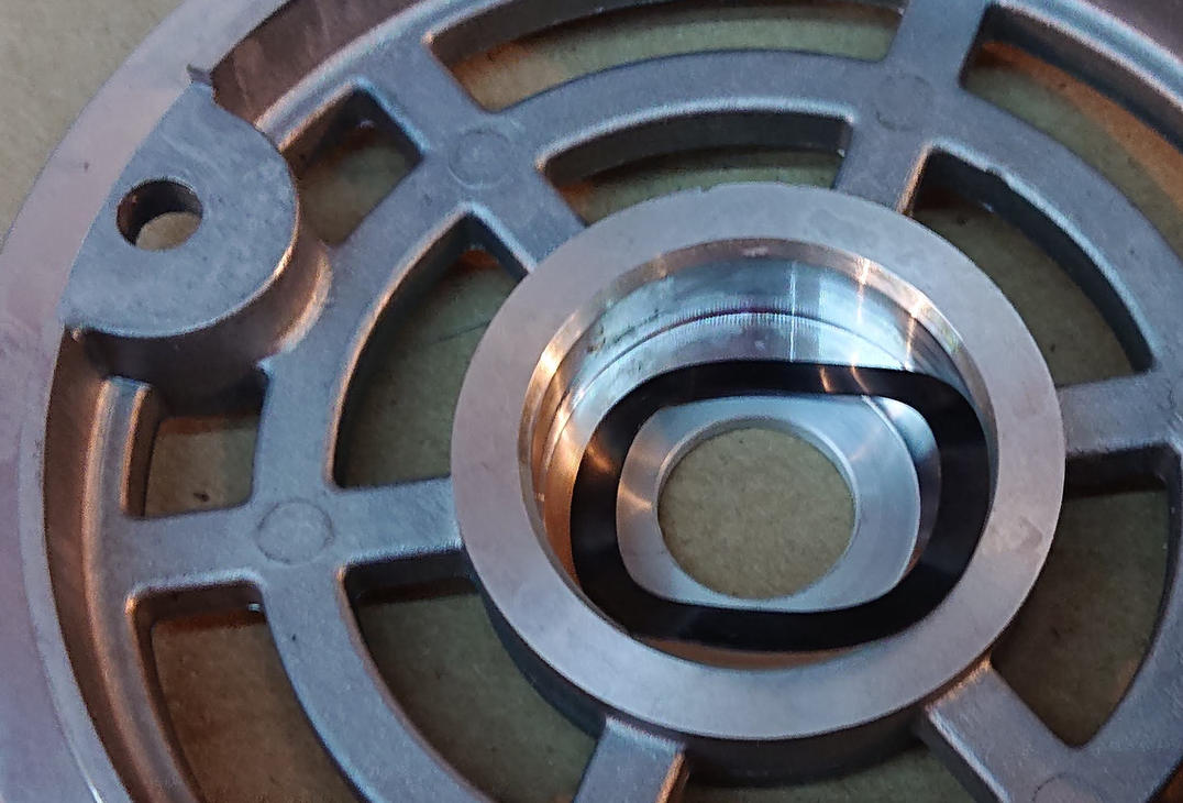
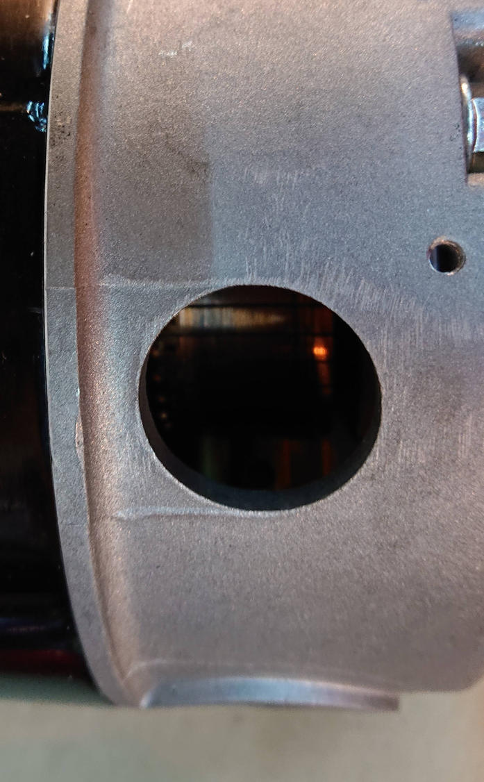
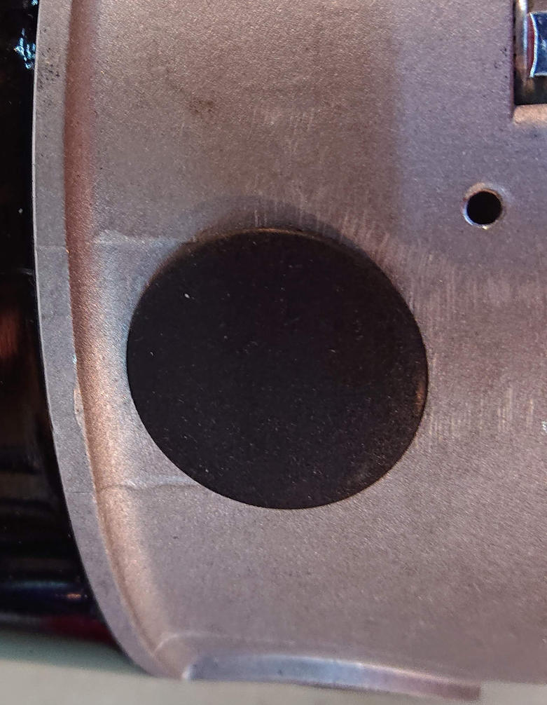
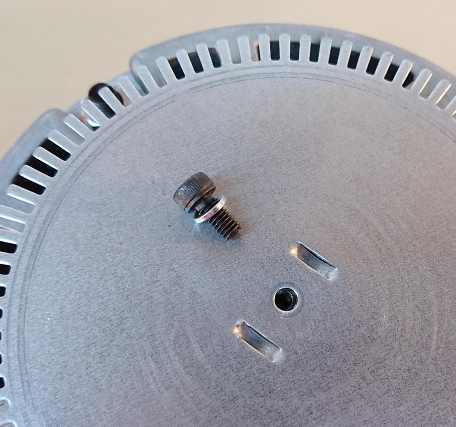
This shows the screw holes in the bell after removing the encoder
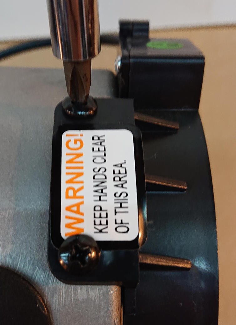
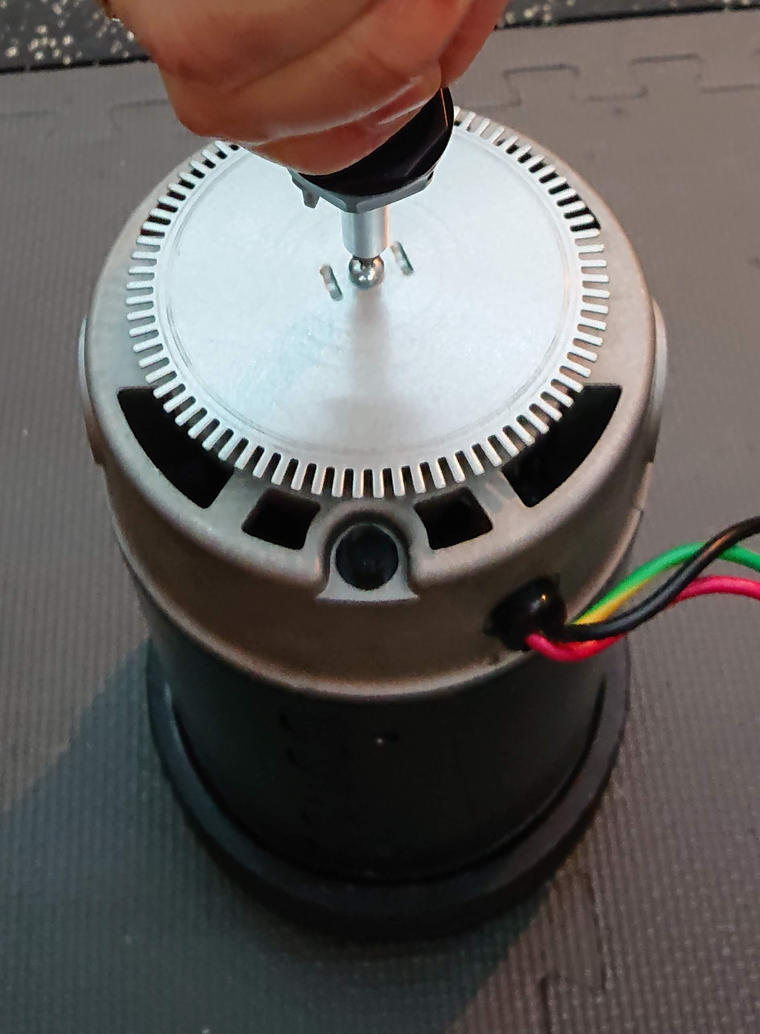
Sadly, the encode wheel is held on with a philips-head screw and is insanely tight.
I had to put the motor on the floor and put most of my weight into the screwdriver to disengage the screw.
The screw is an M4x8 with a lock washer. I have some M4x8 hex head screws extra from a 3D printer project, so I’ll be replacing the philips-head screw with a hex-head screw when I put it back together.
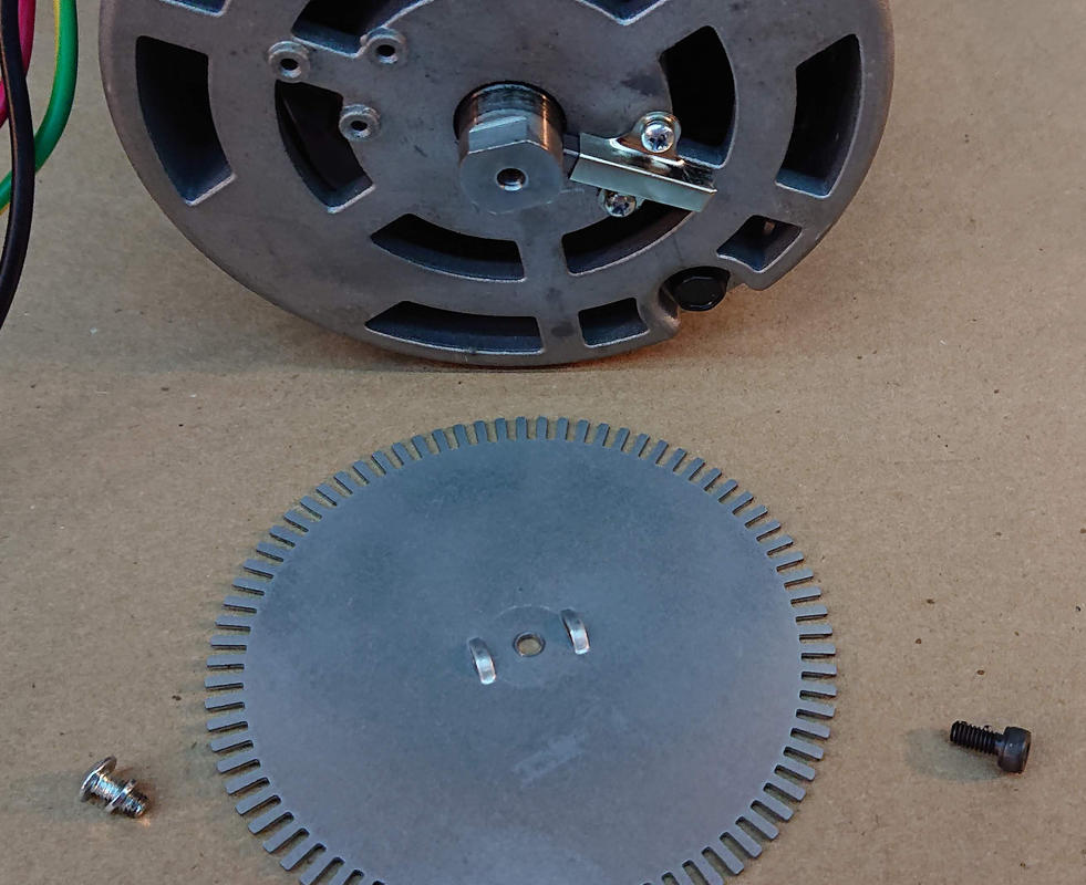
Next, I removed the ground brush that runs against the shaft. More tight screws.
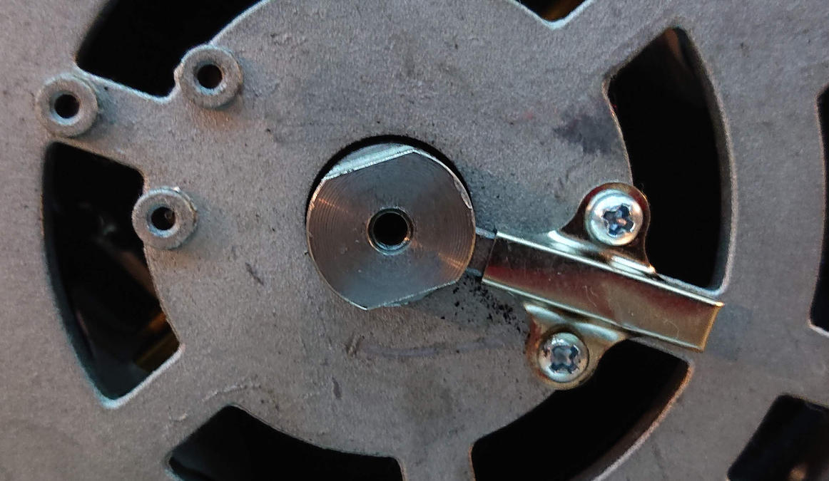
Notice that the brush is scalloped slightly to mate with the round shaft. This becomes important later.
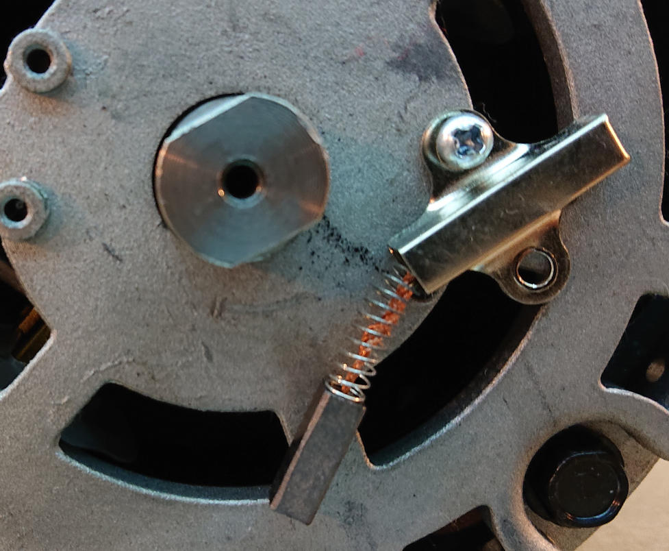
There’s plenty of residue on the shaft to clean off.
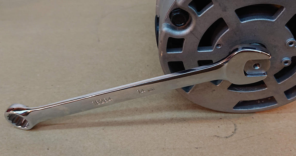
The flats on the shaft that engage the tangs in the encoder wheel fit a 14mm wrench.
…view from the other end…
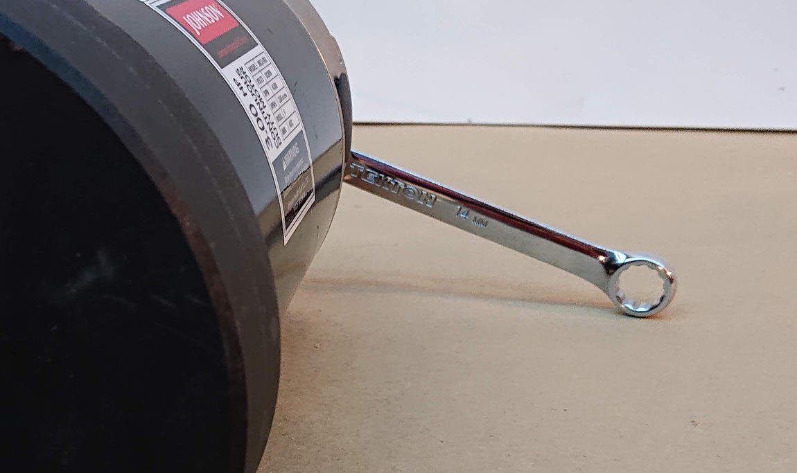
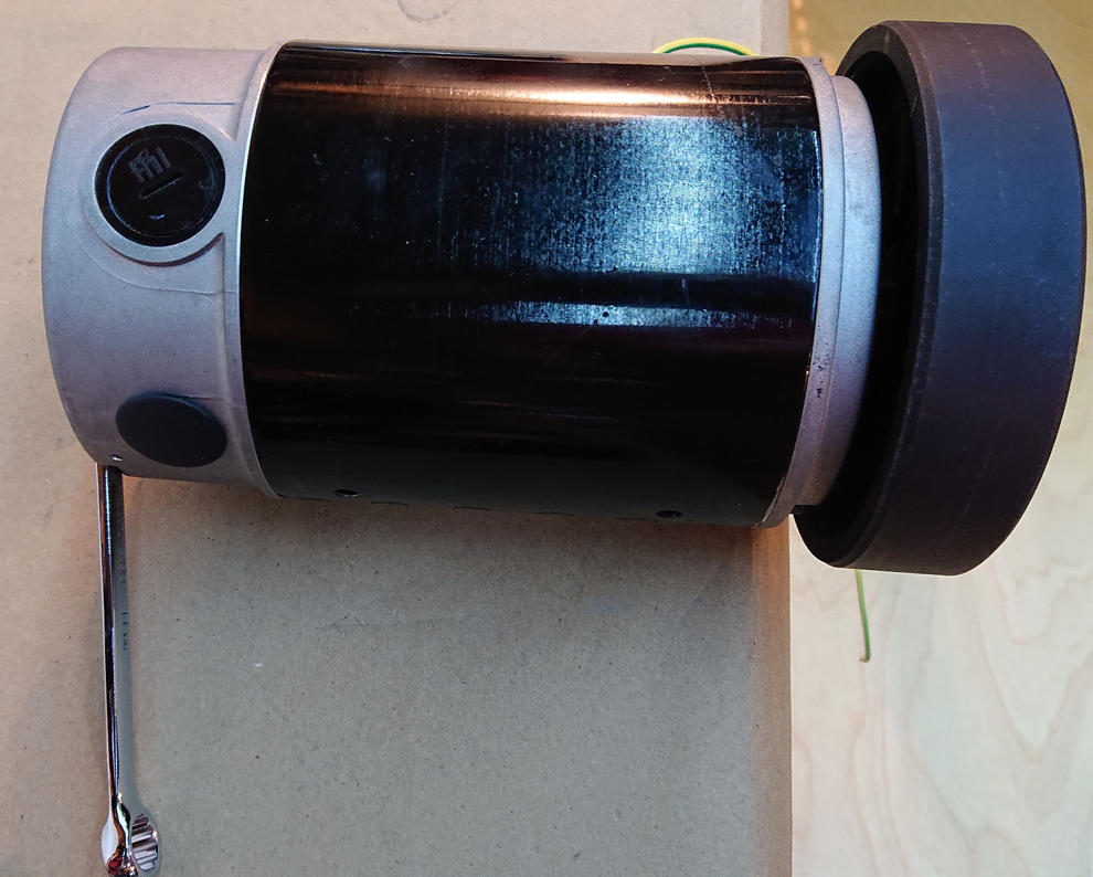
It takes sharp blows with a soft dead-blow hammer while holding the flywheel to unscrew the flywheel from the shaft. The flywheel is held on with a left-handed thread, so it’s backwards from normal. A normal right-hand thread would be tightened if I hit it in this direction.
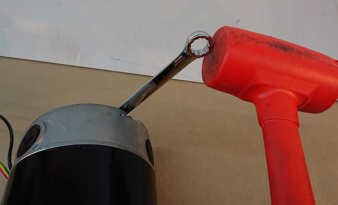
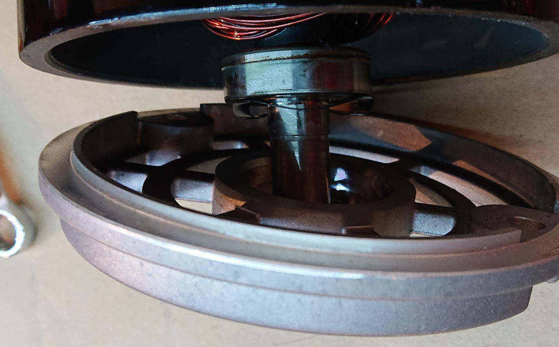
It really took plenty of strength to disengage the flywheel threads, but once it was loosened a bit, the wheel spun right off the shaft. This is the pulley end that engages the drive belt:
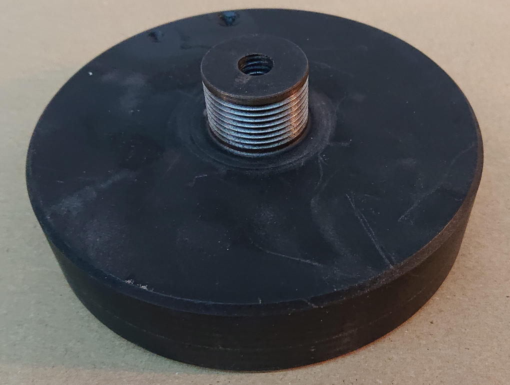
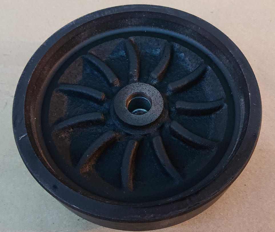
The vanes on the inside are actually the cooling fan for the motor. It’s relatively common for treadmill flywheels to double as the motor fan.
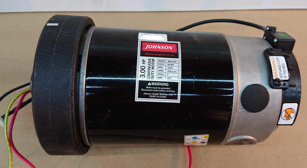
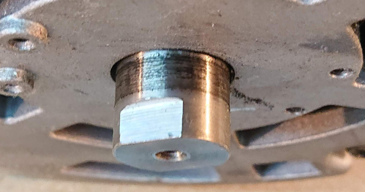
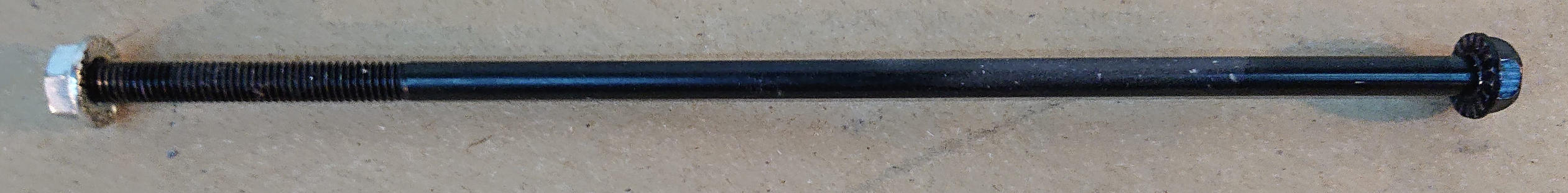
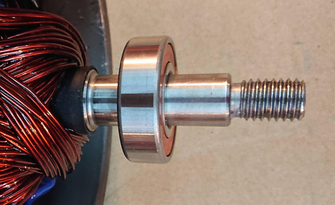
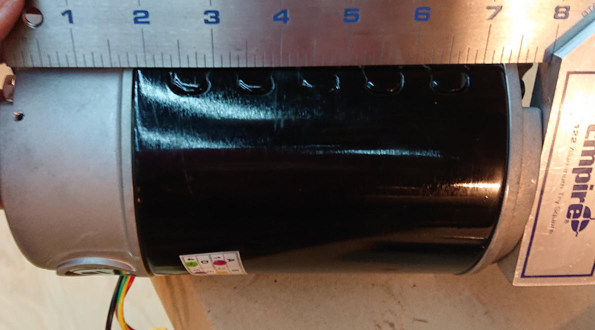
Some people might want to use this kind of motor for something other than a treadmill, so here’s the information on the shaft…
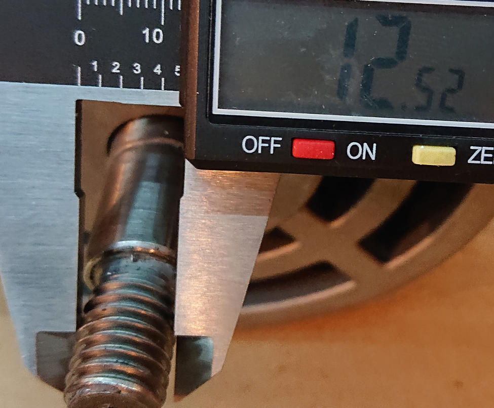
The flywheel shaft sticks out about 44mm from the bell, and the pitch of the left-handed threads is 2mm (measured with a thread gage; no pictures of that).
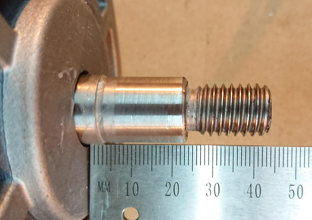
It’s a 13mm nominal diameter 2mm pitch left-handed thread.
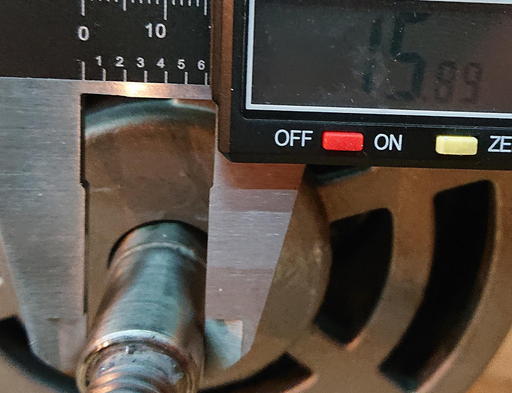
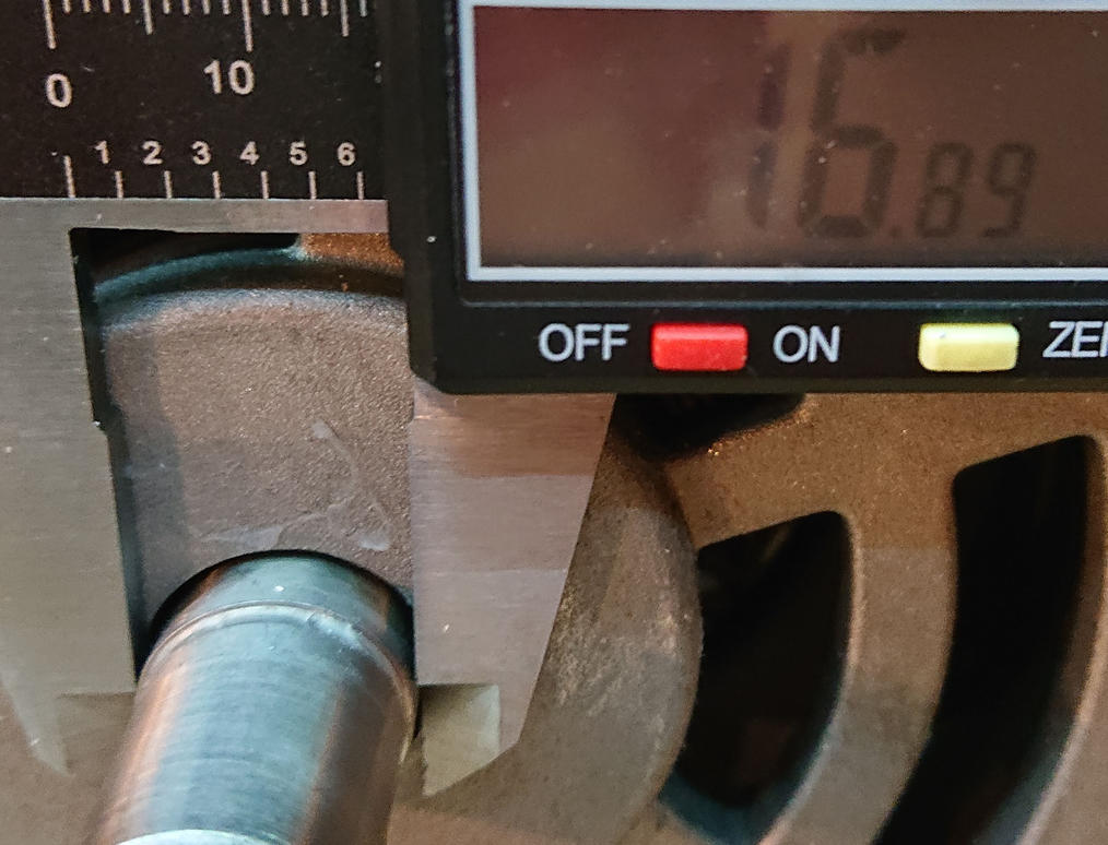
Past the threaded section, there’s a nominal 16mm section that is probably a non-critical dimension outside the bell.
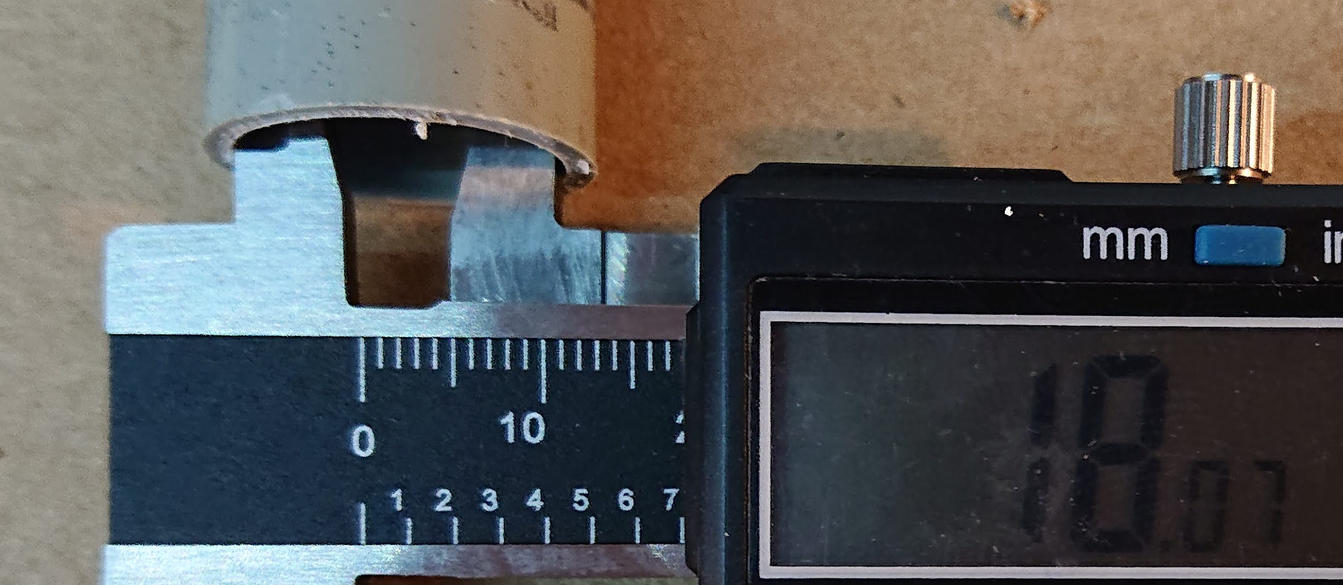
As you would expect, the 6203 bearing rides on a 17mm section.
For clearance, I have 18mm hole bored in the PVC pipe to use to hammer the new bearings into place. This size is chosen to push only on the inner race without damaging the seals. 3/4” inside diameter pipe would have worked fine without boring it out because 19mm is close enough. I just didn’t find any, and honestly was looking for an excuse to use the lathe. But make sure at least the end you hold to the bearing is cut exactly square, use a miter to cut it or just use the factory end.
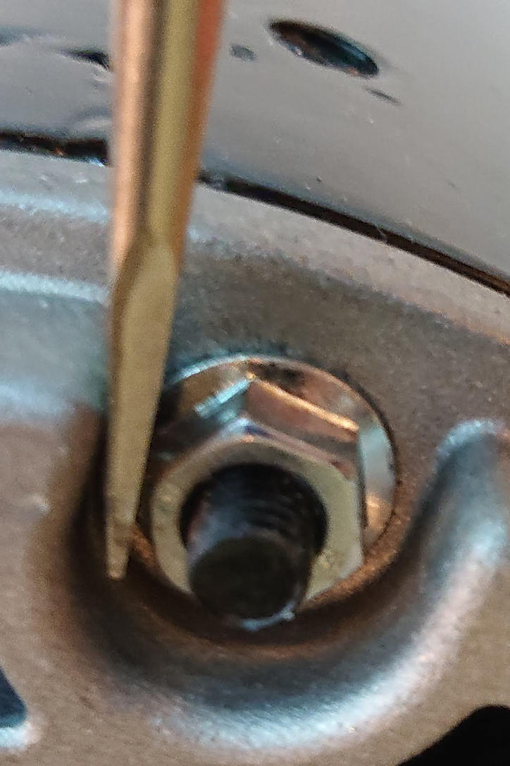
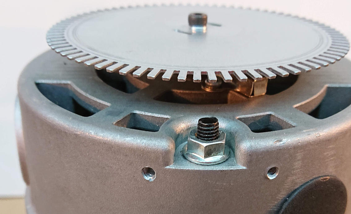
The bolts holding the bells on are held on with nuts without lots of clearance. I found that putting a flat screwdriver blade between the bell recess and the nut worked in place of a thin socket.
On the other end of the motor, the 10mm bolt head had enough clearance for my socket set.
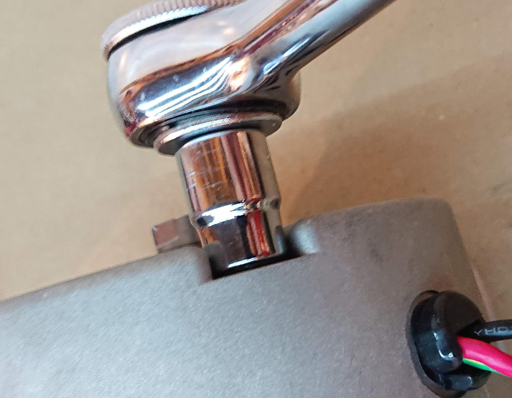
One of the two bolts that holds the motor together.
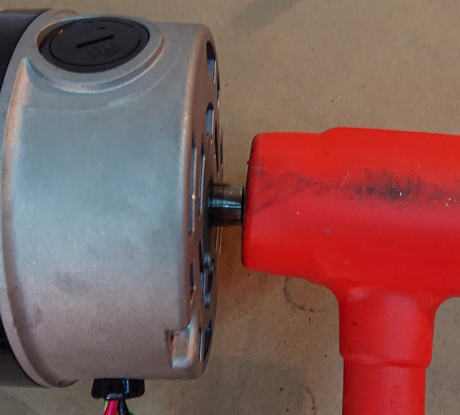
Once I had removed the nuts and bolts, I used a dead-blow hammer against the ends of the shaft to pop the bells off the bearings.
The output end of the shaft has a spring washer between the bell and the bearing.
Here, I have set the washer in askew so that you can see the shape of the washer, It wasn’t actually askew when installed. You can see the polished register that it sits against in the bell.
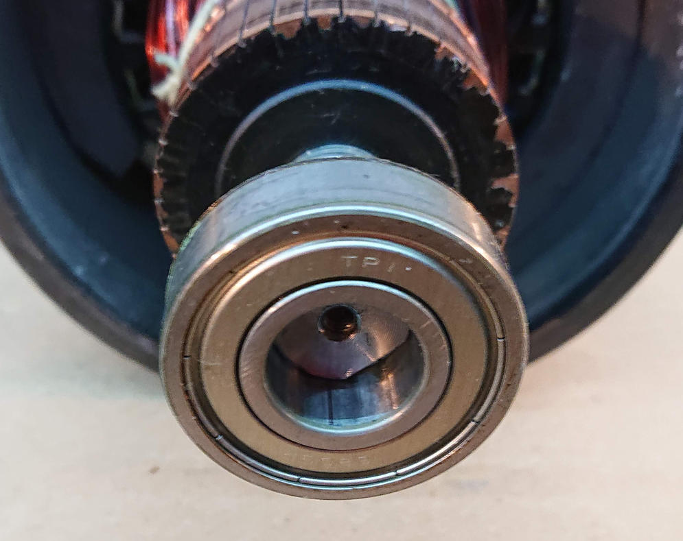
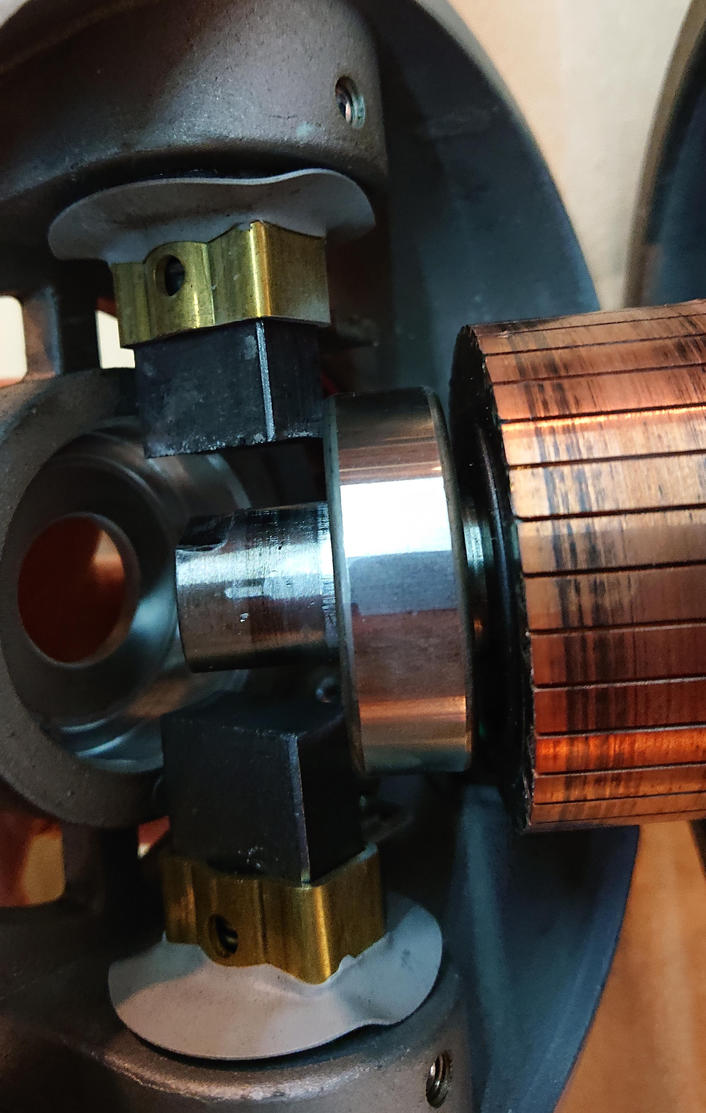
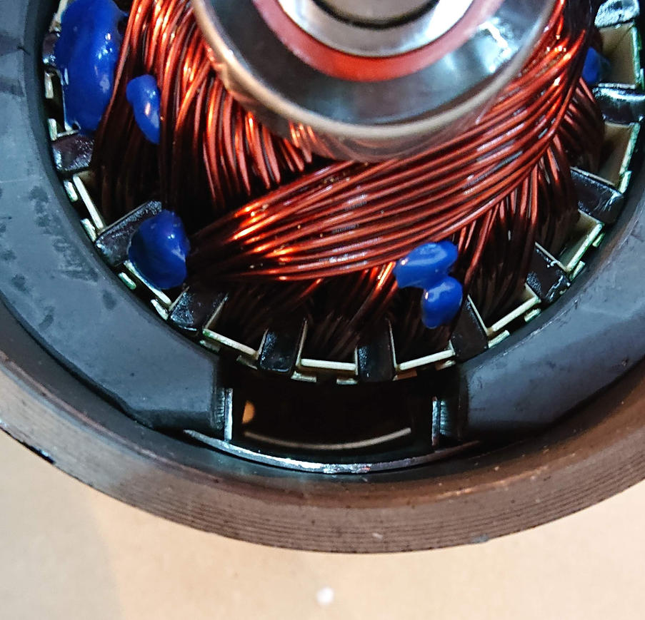
The bearing is fairly close to the windings.
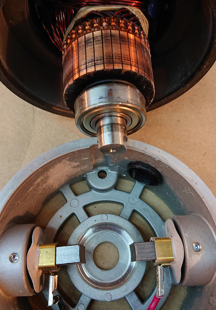
Removing the rear bell with the brushes in it.
This bearing has very little clearance, and no spring washer. You can see that the brushes have lots of life left in them.
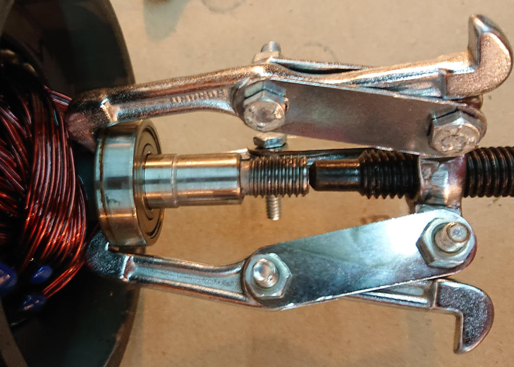
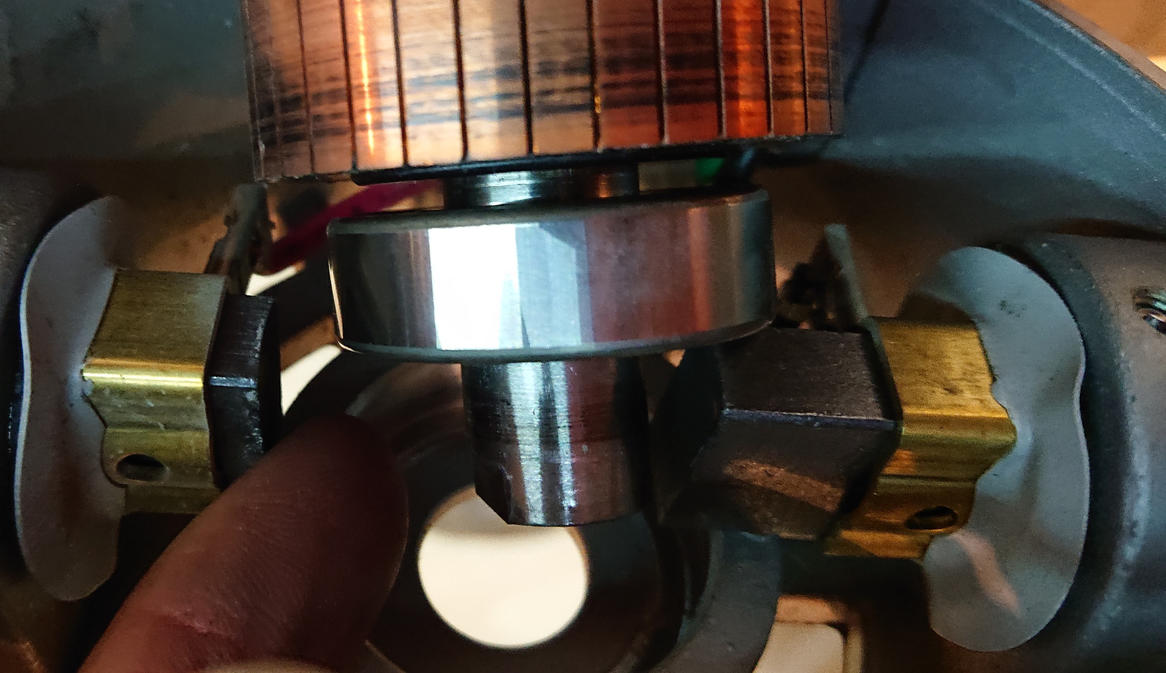
The output shaft has just barely enough room between the wires and the bearing to fit the tangs of a cheap 4” pulley puller. A bearing puller would have been a better choice, if I had been patient enough to order a set instead of grabbing the nearest thing to hand.
Bearing is loose now.
The back side uses a 3” puller, and in order to fit the tangs in I had to cut them down. I did this well away from the motor and carefully wiped off all metal filings so that I don’t get any into the motor. You can see that I was a little bit aggressive with one tang and it bent a little bit. It’s a cheap piece of junk tool, I don’t feel terrible about this.
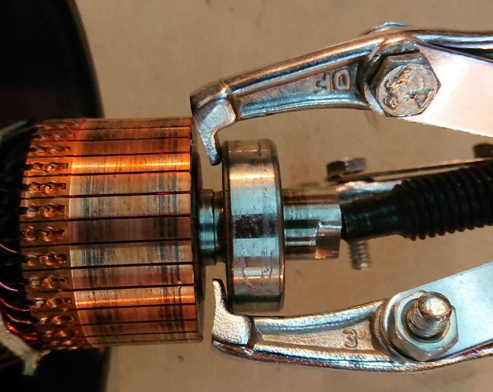
This one is loose too!
The old bearings are sealed on one side, but only shielded on the other. The theory is that shielded bearings need to be re-lubricated, though how one is supposed to do that I don’t know.
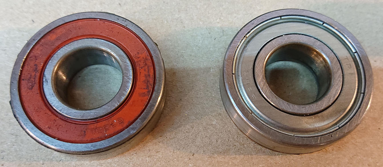
The new bearings are sealed on both sides, which means the lubrication is expected to last as long as the bearings.
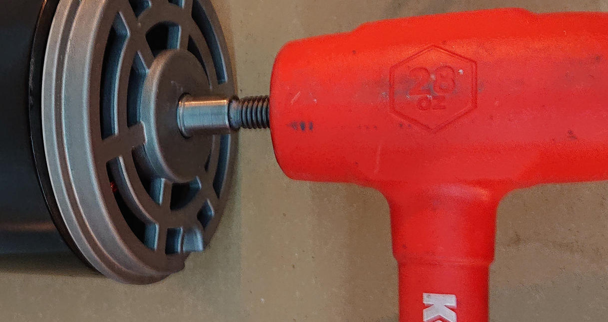
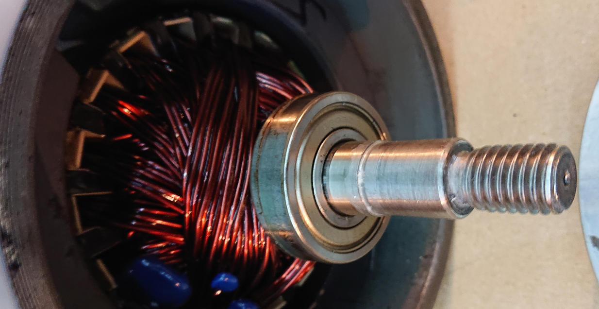
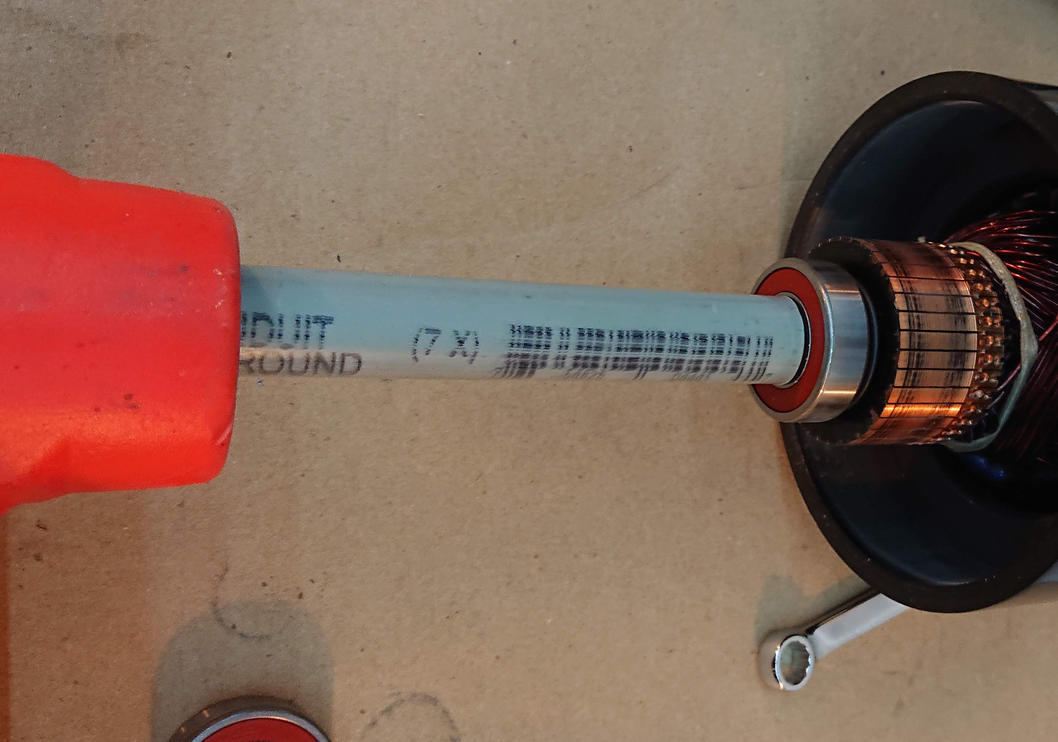
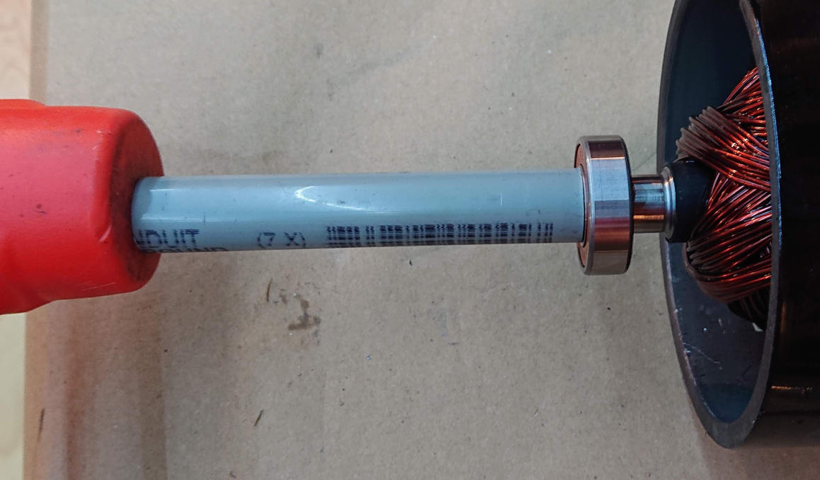
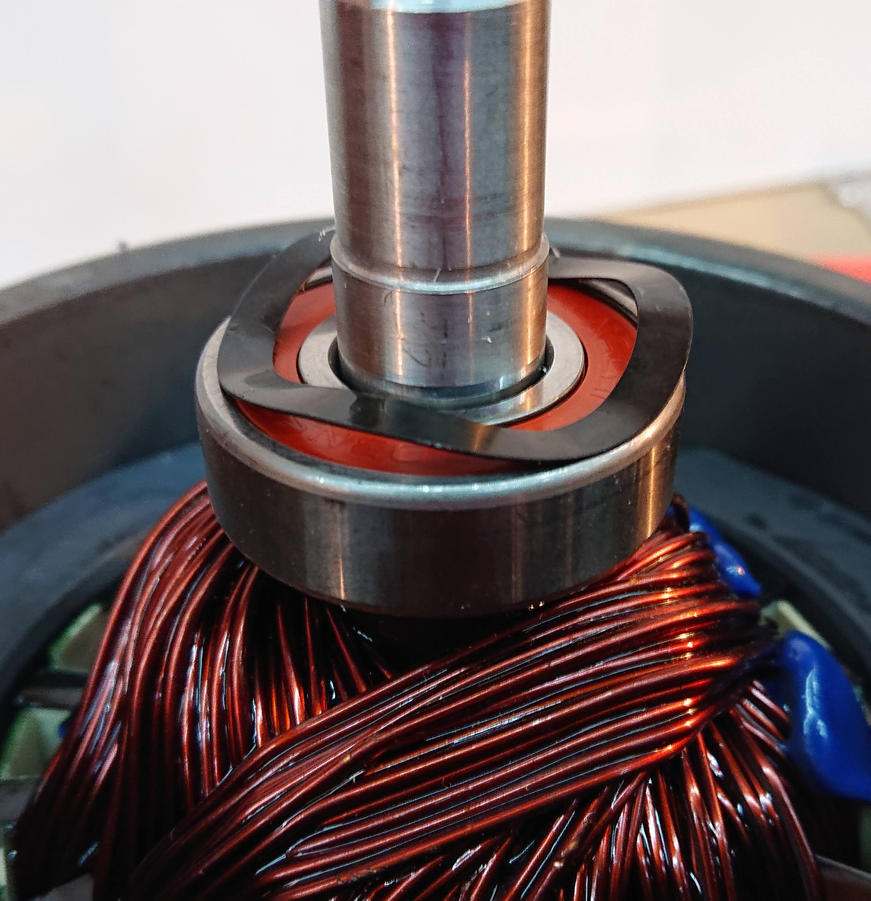
Here’s the setup for pounding the new rear bearing on, using the bored-out pipe to push only on the inner race. I could feel the difference through the hammer when the race seated against its register on the shaft.
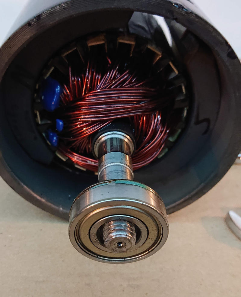
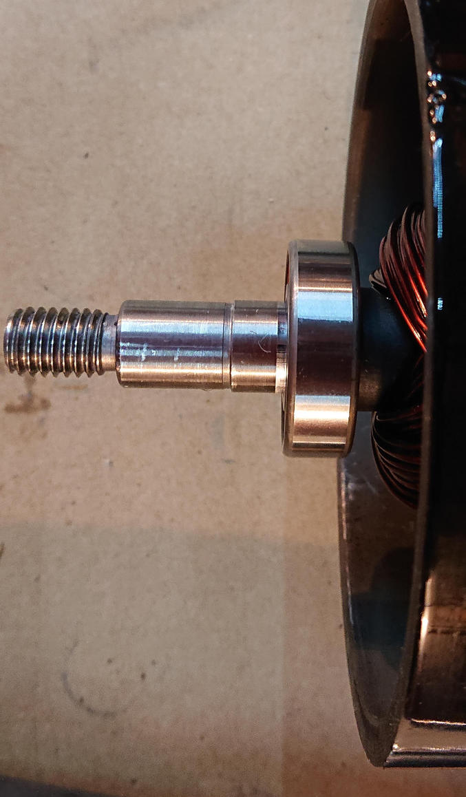
Here’s the output shaft bearing, with the bearing on not yet seated on the 17mm section.
Setup for pounding the output side bearing into place; again it was obviously difference when the inner race hit its register.
Bearing seated. Hopefully not too far in! Makes me wonder if this was originally seated in a jig rather than pushing it to the register? Maybe this is the tolerance that the spring washer takes up?
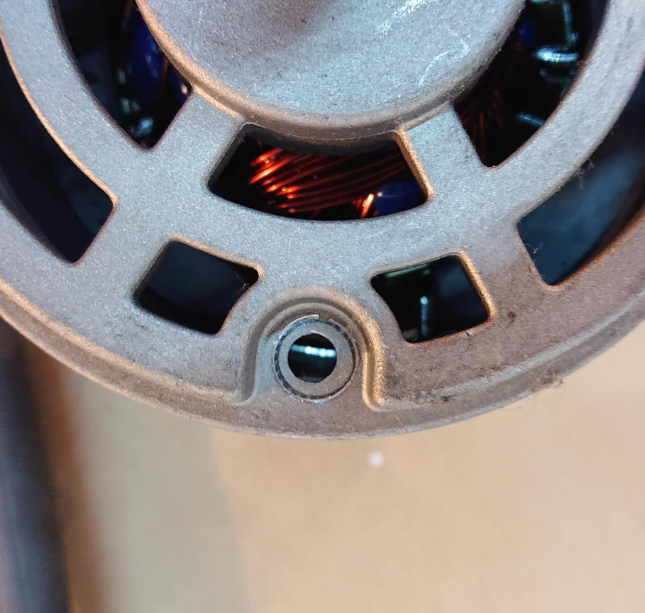
Removed the brush inspection port door to make it easier to move the brushes out of the way to put the rear bell on.
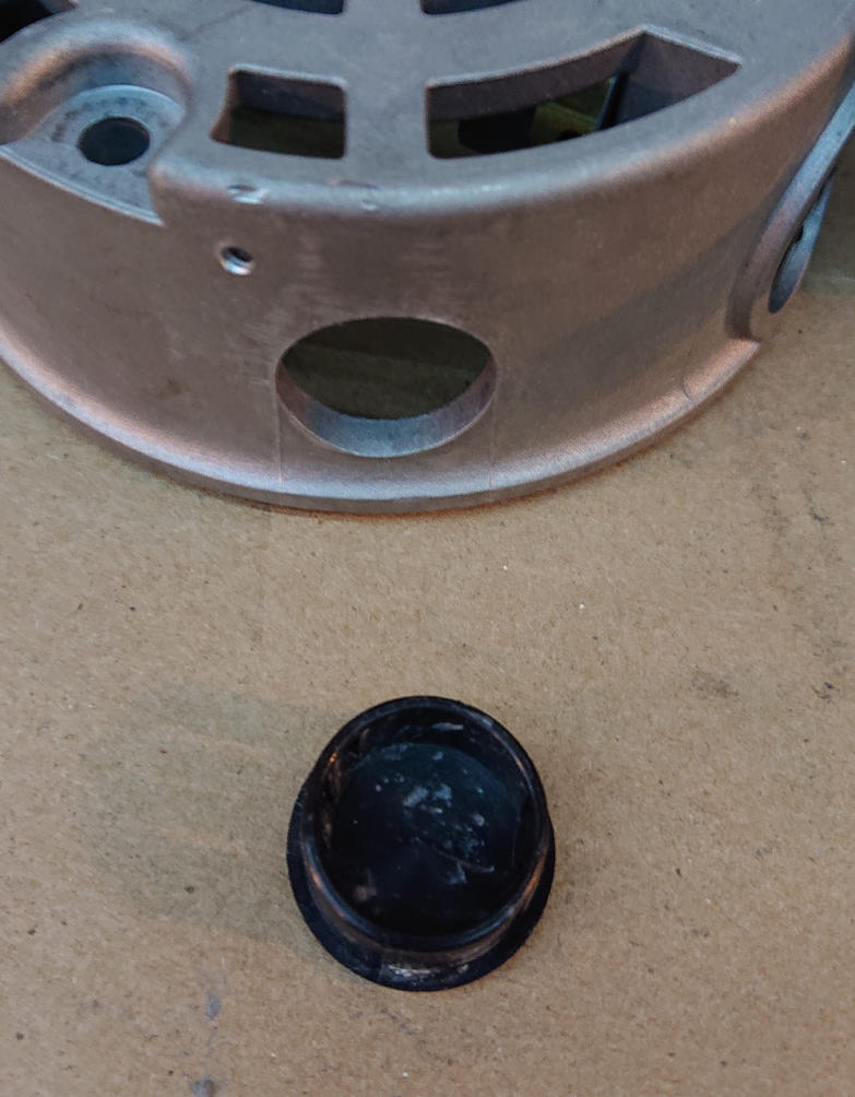
You can see that the brushes won’t fit over the bearing, let alone over the commutator.
I reached in with a finger through the inspection port to move one brush out of the way, then slipped the opposite brush over the commutator, then let go of the brush and slid the bell onto the shaft. Only took two tries to get it right, I think.
View with shaft partially protruding from the bell; it is not tightened on yet of course. So I had to be careful not to let the back bell come off while working on the other end.
This is where the spring washer goes. It really will register properly against the outer race once it’s in the bell, even though that’s not obvious in this picture.
Looking down the motor, you can see a gap between the magnets. This is where the bolt goes.
Make sure that the bolt holes on both bells are aligned with this gap.
I used a square to make sure that the bolts went through square. They are roughly aligned with the housing joint.
I left the inspection port open in case it was useful to see where the bolt was going…
I carefully tightened the bolts, making sure they stayed aligned, until the bells on both ends were flush with the housing. This is seating the bearings in the bells, so it does take some force.
But now I don’t need that hole open any more.
Spin the flywheel on (backwards, it’s a left-handed thread) and tighten it securely. But don’t worry about it being loose; it is a left-handed thread on purpose so that it tightens in use.
Set up on end on the flywheel to install the grounding brush. Don’t drop screws into the motor or you’ll have to take it all apart again to get them out. I’m fortunate that I didn’t make this mistake! Those screws are self-tapping, so make sure you back them off to find the thread to avoid cross-threading!
Make sure that the curved edge of the ground brush is against the shaft.
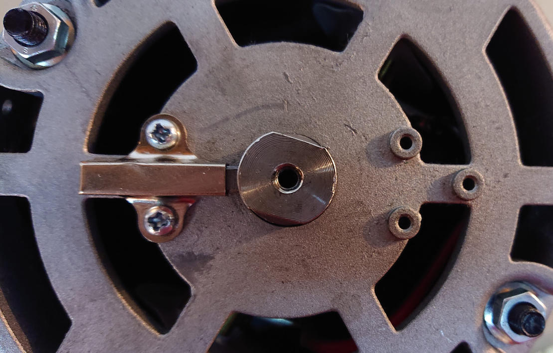
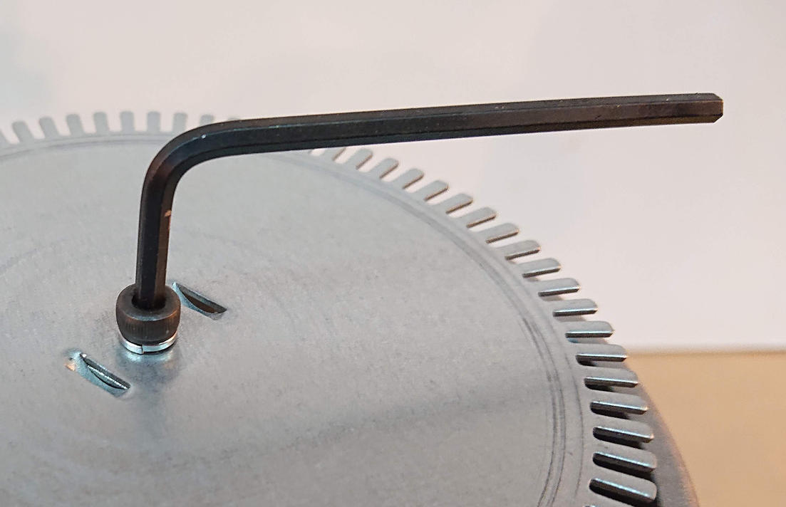
I set the encoder wheel with the tangs engaging the flats on the shaft, and used the hex-socket-head M4x8 screw instead of the junk that was used originally.
Ah, tightening with a hex wrench is so much more secure!
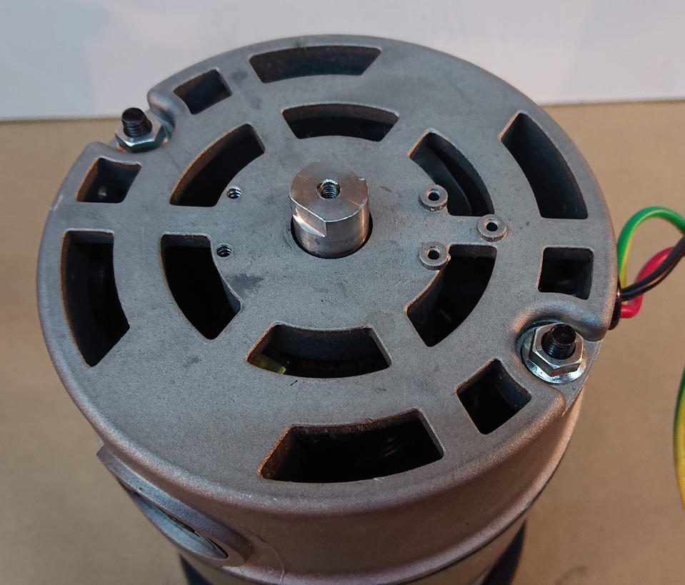
Here’s where the encoder will mount. Those screws are self-tapping, so make sure you back them off to find the thread to avoid cross-threading!
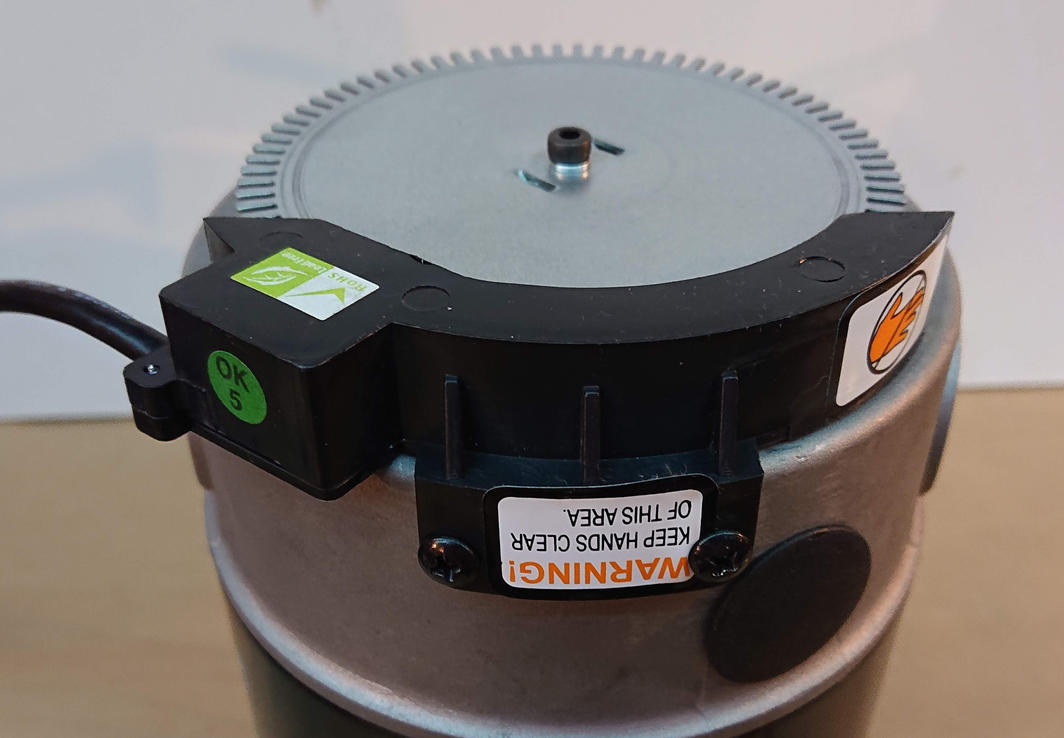
Completed bearing replacement!
The looser bearings mean that when I walk on the treadmill, I can hear some light bearing clicking, but not enough to be annoying.
This time, I tightened just a little at a time until the deck belt was just barely tight enough to not slip while I walk on it. That combined with what I think are higher-quality bearings should make a difference. Hopefully this lasts for the next several thousand miles!